Fatmat followup
Unrelated Preamble
Well, it’s been five calendar years since the last post, hope this one is worth it. Amusingly the first post was right before a major life event and I did some cool stuff after that that I never got around to writing up. Maybe I’ll write about some of the other stuff later.
Version 2 Update
If you haven’t read my original post yet, please do. I promise it is much better written and more interesting than this one, and almost nothing in this post will make sense without it.
While my previous sealed approach worked for a while, both of my V2 mats ended up developing different dead pads that were impossible to service. I’m hesitant to tear them apart or write them off entirely, but they are practically useless at this stage, sadly.
Solder joins are often considered a point of failure in assemblies that will be subjected to rough vibrations, with crimps and lugs preferred. When you have a soldering iron and a lot of solder and heatshrink on hand, it’s tempting to solve all your hardwired connections that way, especially when good quality crimpers are expensive and cheap ones seem to produce terrible results. My takeaway from the Fatmat V2 is if you are going to tempt fate with soldered joins, at least try to keep them in places where you will be able to service them later on if anything goes wrong.
Previously on Stepmania mats:
One thing I’d like to try at some point is covering an entire mat in something like Line-X, perhaps Bullyliner.
A fully sealed mat is no longer something I wish to make - it would be nice if one were truly indestructible, but I thought the Fatmat V2 would be a lot more resiliant than it was, and I don’t think entombing it would make it any less prone to this type of long-term electrical failure.
Version 3
Now for some happier news.
Hardware
Previously on Stepmania mats:
For a yet more rugged approach I’d consider cutting up sheet aluminium and using buttonhead/countersunk screws to attach them to an MDF base, and just have a 900x900mm sheet on the bottom for shielding. Might drive up weight and cost, and require a different surface, but it would be virtually indestructible in situ, and possibly much faster and easier to construct.
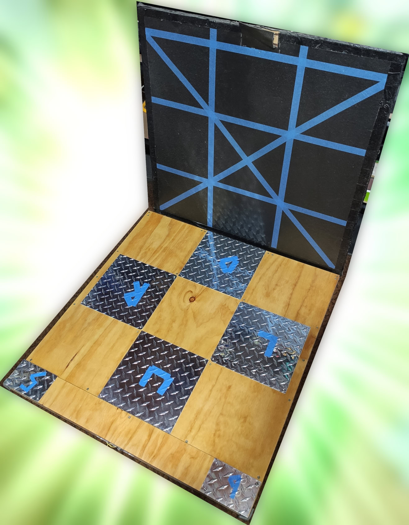
I did this with slightly different dimensions1, and plywood instead of MDF, and it worked out really well! Naturally, the bill of materials ended up a lot more expensive than just using PVA and kitchen-grade alfoil, but propellor plate and stainless steel screws2 look really nice, and I find them comfortable to step on in socks. I originally tried out a clear PVC tablecloth cover, held in by regularly-spaced screws, but it was uncomfortable, and eventually I just took the top cover off varnished the plywood and left the bare aluminium pads open to the elements.
A departure from the previous design is that all the wiring can be accessed by unscrewing the backplate, making it very easy to service when things go wrong. On that note, it did develop a dead pad, and the culprit was a solder join connecting the pad’s wire to a DB-9 connector - reflowing that joint solved the problem. Clearly, the solution here is to use a connector with crimped pins next time! Alternatively, it might be enough to just make my own controller PCB with screw terminals to connect the pad wires to. Any future builds will try to keep any solder joins confined to parts that aren’t subject to the rough vibrations the rest of the mat experiences in use, or at least within a board that doesn’t have components being pulled on relative to it.
Abbreviated Photo Montage
I bought a 2400x1200mm sheet of 1.6mm thick aluminium propellor plate (3003 H224 Grade). Paramount Browns had an on-site cutting service with a guillotine of sorts, and I had them do the two large 940x900mm backplates for me since I was using a sedan (or saloon if you are american) to cart them home. Since they charged per cut, I figured I’d not make them cut all the 280x280mm square pads for me, and just do a couple of 280mm wide strips and a couple of 100mm wide strips - see below diagram.

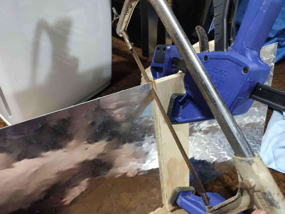
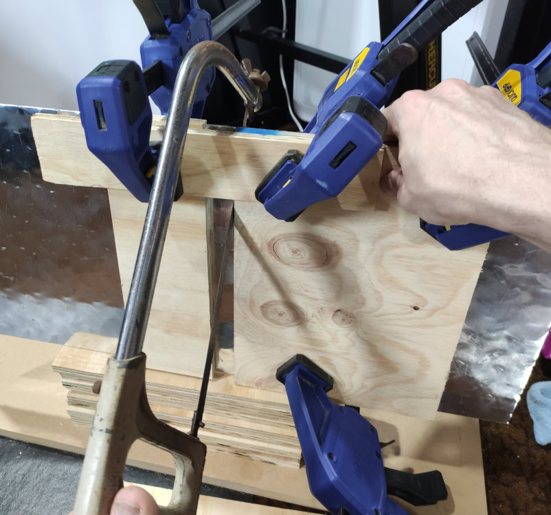 After doing four pads this way, I talked about the progress at work and they mentioned they had a suitable cutter in the workshop to handle it. They didn’t let me operate it, but they did offer to have someone cut the rest for me free of charge, which I was very grateful for.
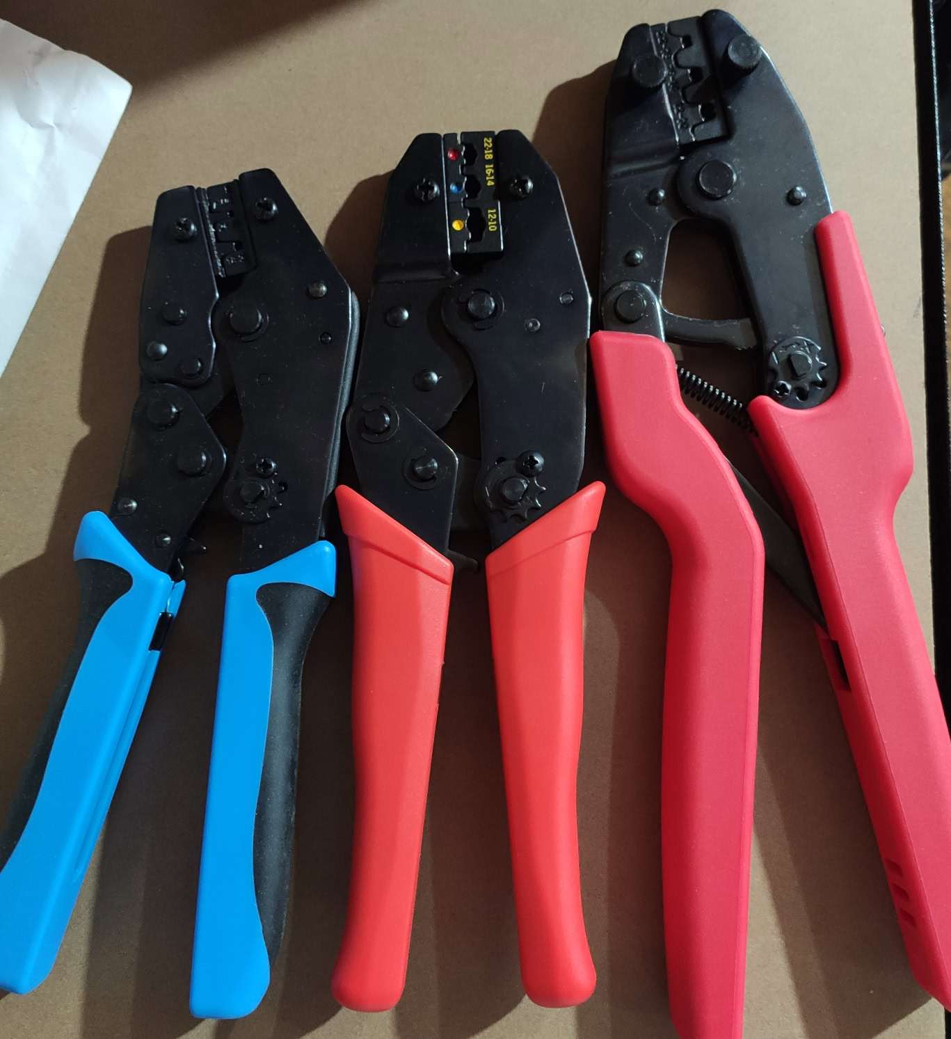
As mentioned before, I went with crimp lugs this time. Here’s the tools I splurged on to make this happen:
 Here’s one of the lugs that sits between the threaded brass insert in the plywood, and the aluminium plate. Each of the pads have one, and the backplate has one which is wired to ground.
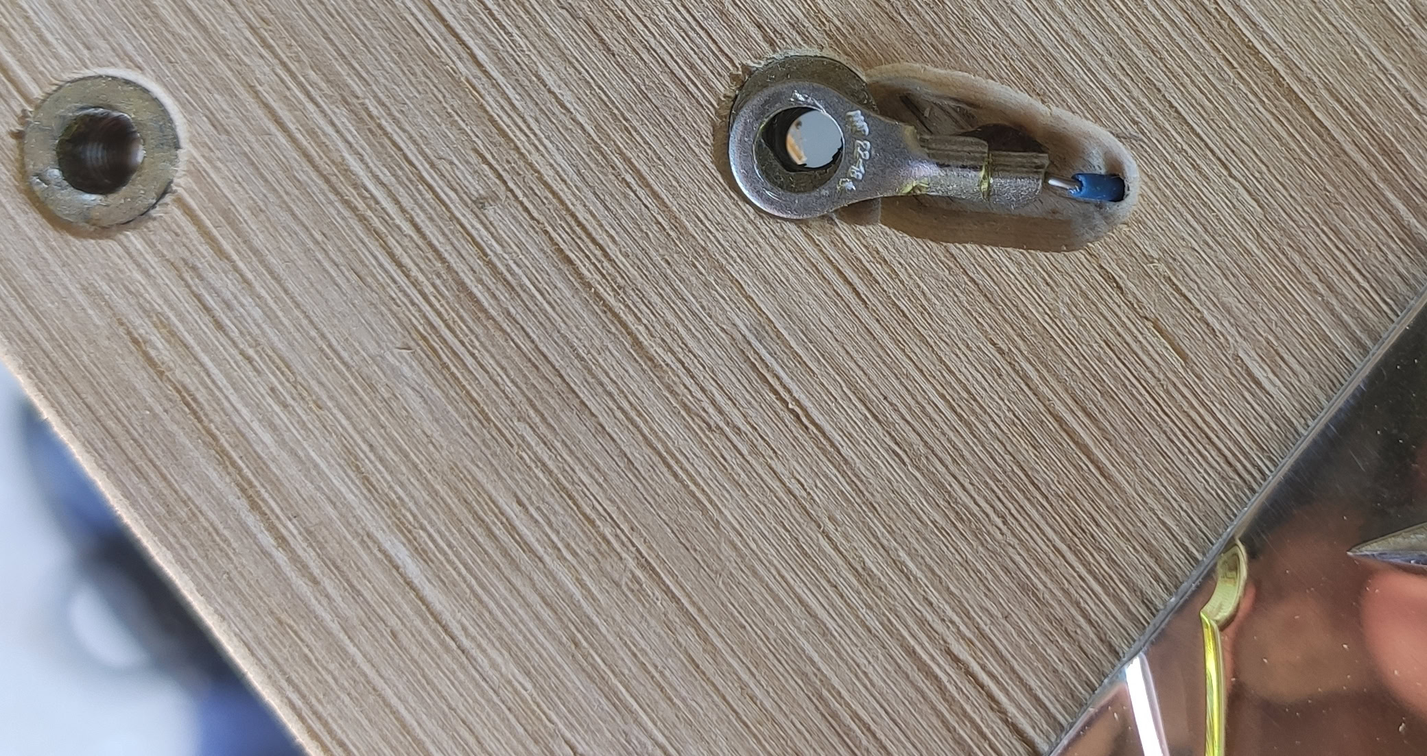
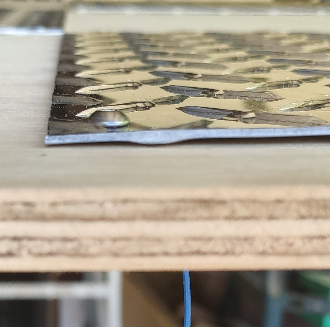
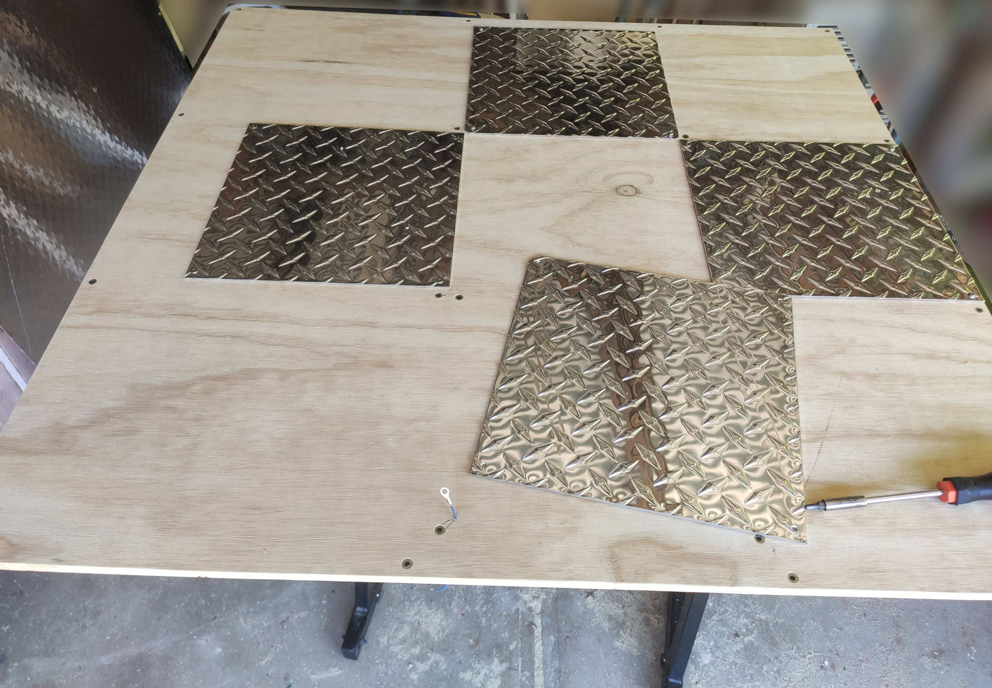 When it’s all screwed together, there’s a small gap between the aluminium and the plywood, but I don’t mind. You can’t see the lug very easily at all.
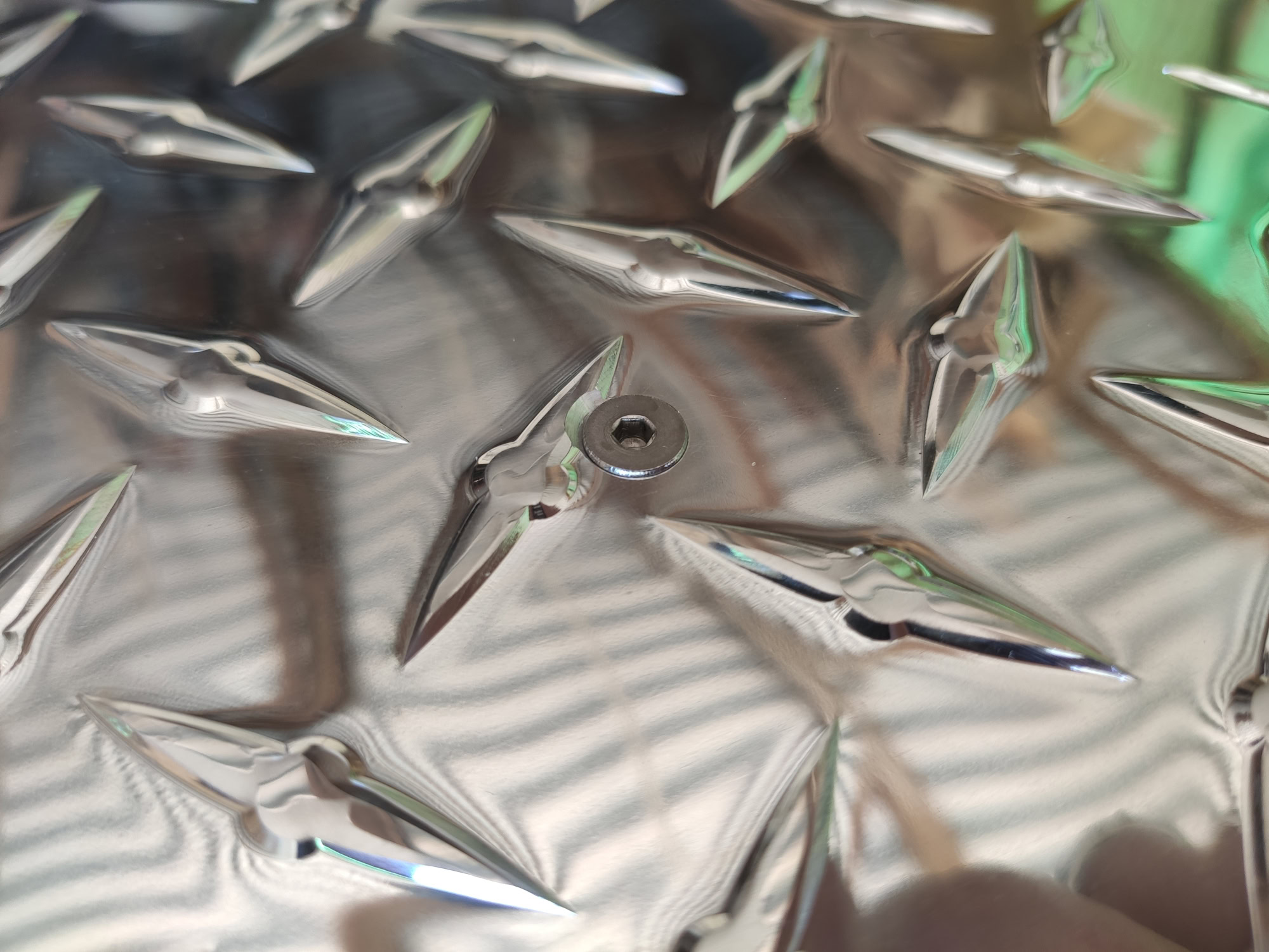
 Here’s a shot of the backplate with a countersunk screw. I love how shiny it is.
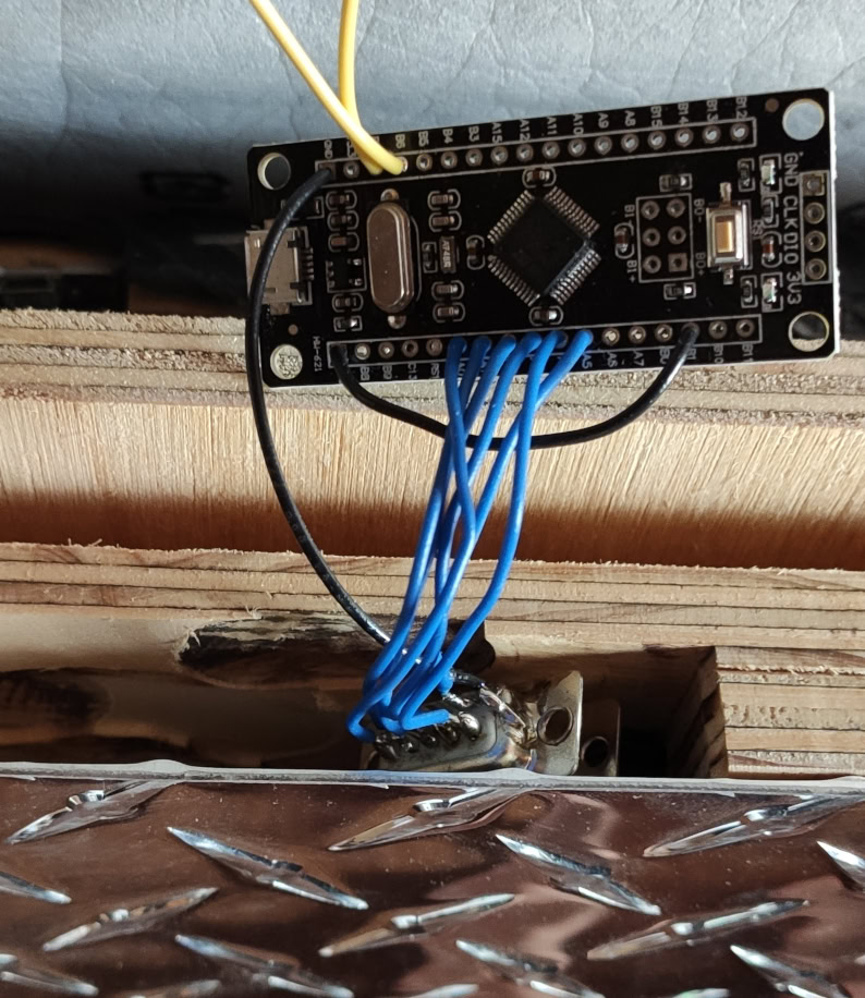
 I used a DB9 connector pair to easily swap out the microcontroller board if anything went wrong later. Getting it to sit right is a pain because I never properly attached it mechanically, but it did what I wanted it to on one occasion, so it was worth the effort.
 Here’s what it looked like when I thought a PVC tablecloth covering it was a good idea. It was slippery and uncomfortable.
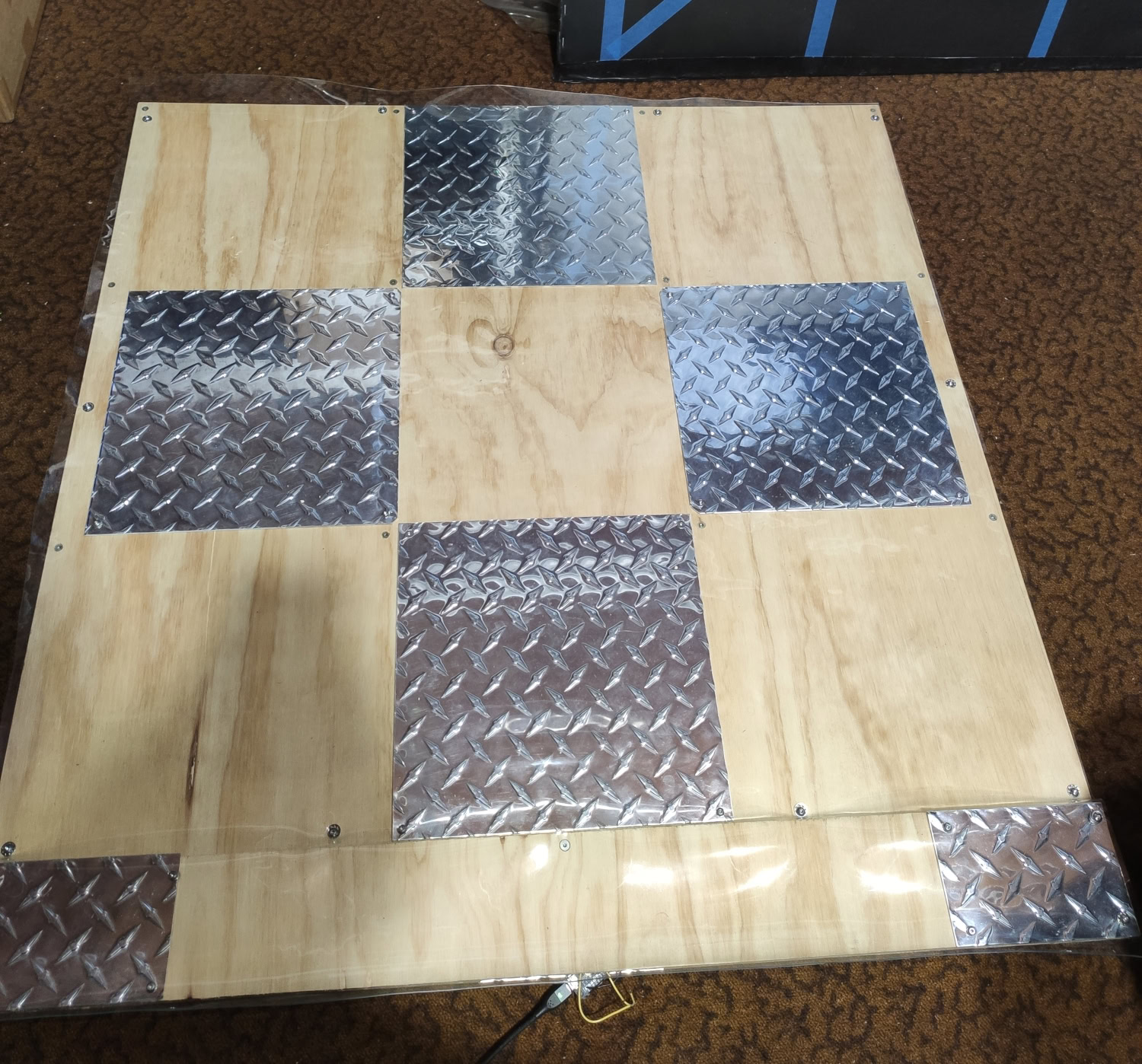 Here’s what it looks like now. Not the best lighting for the photo, I promise it’s much shinier in person. There’s also a Fatmat V2 behind it.
Software
Firmware is mostly unchanged from the V2. It’s not perfect, but it didn’t need any improvements or new features this time.
Previously on Stepmania mats:
Unfortunately, I don’t have a good solution for a calibration routine on the controller alone - I’d much prefer to integrate something into Stepmania that would show on-screen arrow prompts.
Since then, I have made a rhythm game in Godot 3.x based on a different arcade game. I laid a lot of groundwork in it for Stepmania chart support, but I never completed that at the time. Stepmania itself has gone through some strange times since I last talked about it3. Depending on how this year goes, I might finally get around to properly implementing a Stepmania game mode in my rhythm game, and then I can follow my dreams of tighter game-controller integration and maybe leave out the dodgy-looking recalibration wire pair or button.
Speaking of dynamic calibration using game-controller integration, the sensitivity on bare aluminium pads is unsurprisingly fantastic. I’m still playing with socks and no shoes, but shoes would not pose a problem at all to this hardware, it’s just the usual problem of performing a calibration which is suitable for shoe-clad play that isn’t overly sensitive for socked or nude play and results in hover detection. Playing with shoes is highly desirable, especially when dragging these things out to events, so I look forward to being able to accomodate both without reflashing firmware to tweak thresholds.
Next Mat
As good as the Fatmat V3 has been, I’m not content to stop there. It’s a simple, solid design that I may make more of at some point in the future, and I’d definitely recommend it over the V1 (I would not say that for the V2), but I anticipate some different personal requirements going forward.
Form Factor
Previously on Stepmania mats:
Portable mats for travel would be nice. I’m teasing out ideas for step sensing on 30x30cm garage plastic flooring tiles, which pack up quite nicely from a purely mechanical standpoint.
When I wrote this, this was only about taking it out to other people’s houses for parties or whatever. These days, I’m trying to move overseas, so it’s even more important to me to throw away giant monolithic mats and make something nice that can pack into airplane luggage.
I still like the concept of the 30x30cm plastic interlocking flooring tiles, but I haven’t thought of a good electrical connection for them all, and its possible that most of them will become loose after tens of connection cycles.
Game Flexibility
So the classic multi-use concern for Stepmania mats is 4pad (Dance Dance Revolution) vs 5pad (Pump It Up), which results in the 9pad compromise - a 3x3 layout of equal-size square pads that works perfectly for 4pad gameplay and the 6pad variant (DDR Solo) which adds the forward diagonals, and can sort of work for the 5pad layout.
The true 5pad layout has taller pads for the diagonals, which would encroach on the left/right pads, and while I’ve never played on it, I assume that can be quite meaningful.
Now, I don’t actually care about 5pad gameplay, but if I can incorporate it for free™, I won’t leave it out. What I actually care about is another game called Dancerush Stardom (DRS), which replaces traditional step-on-pad gameplay with more freeform column gameplay, like a foot version of Chunithm. A true DRS controller uses an infrared border surrounding the dance floor (more on this in a future blog post) which can accurately determine multiple obstructions in the contained area - the official arcade cab supports two players, so four feet, but it’s not unusual for that hardware to support 10 or more at a time. It also has a fancy light array underneath it, so it’s quite stimulating.
The dance floor unit for a DRS cabinet has outer dimensions of 1480x1940mm, and the inner dimensions are probably around 140x180cm. The width is the important part, the depth is designed so that two people can play one in front of the other, so something like 120x90cm would probably be quite reasonable to play on instead (4 wide 3 deep of the 30x30cm tiles).
Sensors and Circuit Topology
The actual DRS gameplay is coarse enough that 12 discrete column detectors should work just fine, so this leads me to an interesting idea - how about dividing each 30x30cm tile into 4 rectangular sensor strips?
- For 4pad gameplay, just make them act as a single pad, the small gap between them shouldn’t harm that.
- For 5pad gameplay, the top and bottom of the left/right tiles can contribute to the respective diagonal pads.
- For DRS gameplay, the 3x4 mat can be rotated to the side, and now it has the columnnal resolution required.
This would require enough microcontroller pins to scan 3×4×4 = 48 capacitive sensors. Doing it with a single microcontroller is possible, but it would be a wiring nightmare, and that adds interference concerns, so it’s likely best to have one microcontroller per 30x30cm tile, and have them communicate with each other over the smallest number of connectors we can manage.
Number of Wires
1) Possible as a modulated power bus with a common return plane elsewhere. Bad idea. 2) Modulated power bus works quite well in some contexts. It adds implementation complexity and has poor maximum bandwidth. 3) Power pair + a self-clocked signal. Most realistic option yet, but still potentially hard to pull off. 4) Power pair + data pair, possibly something like I²C bus. Easiest option so far, bandwidth should be sufficient. 5) I’m not sure what I’d do with a third data wire. 6) Power pair + 4 communication wires, probably SPI. I think this is too many.
At this stage I think the best compromise is four wires.
Electrical Connectors
Possibly pogo pins on the side of the plastic tiles. This might be too ambitious though, I can tolerate a little bit of setup+teardown complexity in the form of plugging in small ribbon cables or 3.5mm TRRS connections underneath the tiles if it works out to be more reliable and easier to assemble in the first place than other solutions.
Topology
A full mesh setup where each tile has connectors on all four sides and forms a grid has some appeal in simplicity and homogeneity. It’s also a bit wasteful when I could just have a columnar setup where each tile has connectors on one axial pair of sides, and then have something to connect all the columns at one side. I don’t want to hardcode logical addresses so whatever I do will need to be able to autonegotiate addresses based on physical layout at runtime - this will likely require each controller to have multiple I²C busses rather than just passing a shared bus through the entire column or grid.
Something will need to present a USB device port, naturally. The efficient approach here would be to have a separate device that connects to a tile, possibly multiple columns of tiles. If I’m still using something like Black Pill boards for the microcontrollers, each tile will have a microUSB Type-B port anyway, so that plus the full grid layout could make for a trivial homogeneous setup where any tile can be used as a device master.
Closing Thoughts
Chances are, the next bit of actual work in this area will be on the rhythm game. I’m a bit out of shape and I want to get back into Stepmania, but Stepmania itself is a bit crashy for me on startup and can be a frustrating experience restarting the game until it decides to work, going between the mat and keyboard each time. I’m not aiming for 100% Stepmania 5 compatibility, since I don’t really care about novelty effects and scripts, just the basic note charts and the tempo changes.
I’ve written this years later than I should have, so many details were glossed over compared to the Fatmat V2 build log simply because I’ve forgotten the narrow strokes, so to speak. If any of the missing bits are of particular interest to you, I’m open to most questions on this topic and may be able to remember or deduce some specifics when probed.
-
94x90cm, the added centimeters are to accomodate raised Start/Back buttons and a protected cavity for the microcontroller board. ↩
-
I haven’t noticed any corrosion yet, but dissimilar metals in this configuration could be an issue. The lugs are a different metal again, so it was never going to be a single metal stack, but this is something to refer back to if things get ugly in another decade. ↩
-
Stepmania briefly backed a fork as the successor, but was forced to retract that when the project’s claims of eventually going open source didn’t manifest. That fork is proprietary to this day, which I guess is another success story for the BSD/MIT lads. ↩

