LHW Fatmat V2 build log
Introduction
This is a build log of my most recent (as of August 2019) custom Dance Mat controller for Stepmania. It is the second of its kind, and the fourth mat I have constructed. It has proven reliable over a few months of usage to the point where I felt comfortable creating a second one, and recording the process to aid a certain friend who aspires to build a mat of his own. I will likely not be creating any more of this exact design, for reasons I will delve into later, however I believe this to be a rugged and reliable DIY design for barefoot and sock play and would not hesitate to recommend it to people with sufficient time and money on their hands.
DISCLAIMER: This post is not intended as an introduction to electrical/electronic concepts and some terms may be left unexplained. Even so, I hope that my explanations and photos are sufficient for a reasonably curious hobbyist to be able to seek out any gaps in their knowledge elsewhere and be able to construct such a device themselves if they so desire.
Background
Stepmania is a rhythm game much like Dance Dance Revolution1. Players step on four floor pads as dictated by scrolling arrows on-screen, set to music, and are judged on their timing. Naturally, this requires special controllers2 of which there are few commercial options. These controllers are often called softmats or hardmats depending on their construction, and more generally pads. Softmats are flexible, usually made of fabric, low-cost, lightweight, foldable/rollable and somewhat lacking in durability as a natural consequence. Hardmats are rigid, higher-cost, heavy, less-portable and somewhat sturdier affairs. Given the choice, I’d imagine most people would rather play on the latter, though they may not necessarily want to own one. If the name Fatmat led you to believe that this is going to be a thick, solid piece of hardware best described as a hardmat, then you’re on the right track.
One can obtain chinese softmats for around AU$25 on eBay or similar. If you’re willing to pay more than double that, you might even be able to find a double mat. I started off with one of the AU$25 ones, it was enough to get me hooked on the game but quickly developed problems that inspired me to get something better. With a bit of modification you can get them to velcro to floor carpet to stop sliding around, or staple them to hardboard (aka masonite) to turn them into a pseudo-hardmat with a life expectancy beyond a month of usage. They aren’t designed to be played with shoes on, and the top surface can be a tad unpleasant with socks on.
Hardmats are a bit rarer, there’s a few people making different ones for hundreds of dollars and there’s the option of obtaining a DDR or In The Groove3 Arcade Cabinet which typically run for thousands of dollars. I have no hands-on experience with any of these commercial offerings, and all of the mats I’ve built so far have been hardmats, including this one.
Concept
The mat detects the presence of a player’s foot on certain locations of the top surface, and converts this to “button presses”. It achieves this by crudely measuring the capacitance of conductive (in this case aluminium foil, henceforth “alfoil”) pads embedded beneath the aforementioned locations, and registering abnormally high capacitance values as foot contact.
This method of capacitive sensing has zero moving parts and the mechanically fragile alfoil sensor pads require no contact, which allows them to be situated in a well-protected location where nothing can get at them. It also makes for a very simple hardware design using low-cost materials. Unfortunately, the presence of the player is not the only thing that will influence the apparent capacitance of the sensors - drops of water on the play surface can be indistinguishable from a player’s foot, the sensors act as antennae for various sources of electrical noise by their very nature, and the player’s proximity to other conductors will influence their net effect on sensors4. These difficulties are up to the microcontroller to solve, but I’ll happily take some software complexities over hardware complexities as they don’t need to be replicated by hand for each mat made.
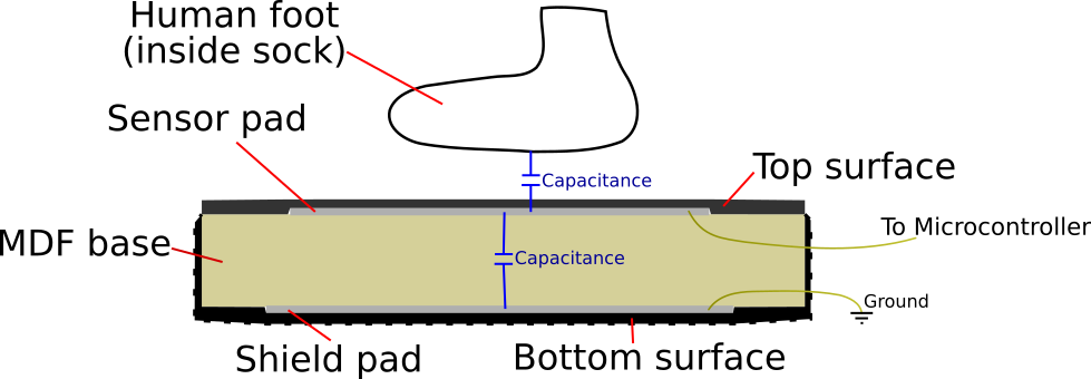
The cross-section of an imaginary mat consisting of a single sensor pad is illustrated below. The blue capacitor symbols do not represent the physical components you use in your circuits but rather the major capacitive effects acting on the sensor pad.
Dimensions
I’ve never measured a DDR arcade machine myself, so I just went off of the measurements on this page. I only care about the pad size (11” square = 28cm square) and to a lesser extent the gap between the two controllers (1 13/16” = 4.6cm). The other borders are completely arbitrary as far as I’m concerned, so I take no note of them. I use 28cm square pads and the left/right pads have 2cm to the edge of the MDF base, and the material that rides up the sides of the MDF is close to 3mm thick, so if you put the two Fatmat V2s together, it’s almost exactly the 4.6cm gap of a DDR machine!
Construction
When I made the Fatmat V1, my first attempt at making the MDF base was unsalvageable. This resulted in an embarrassing second trip to Bunnings, and the shame imprinted on me deeply enough that I doubled up when making bases for the Flatmat and Fatmat V2. In the case of the Flatmat, preparing two bases at once made clamping for gluing quite convenient. In the case of the Fatmat V2, I did some fancy woodwork to better integrate the electronics and also edge-routed a round edge along the bottom to make the underside fit nicer. A lot of the woodworking time was setup and pack-up, so doing two bases at once was something along the lines of “buy one, get one 80% off”. Who doesn’t love a deal like that, especially if they want to maybe have two matching mats at some point for doing doubles, right?
Anyway, the reason for that preamble is that this write-up starts with an MDF base that I cut to size and routed early this year, without any nice documentation. It’s been sitting around in my room for months and has some skid marks which may have been there when I bought it or may have something to do with the first Fatmat V2 resting its rubber underside on it. The good news is that if you don’t want to route your MDF base, you don’t have to, and depending on your local Bunnings you may not even have to cut it to size yourself. You may well be able to start off straight from this point too!
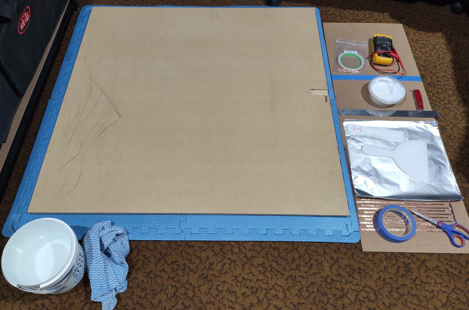
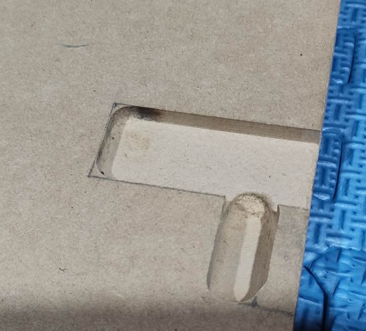
Optional routing. This is the house that my microcontroller will later call home.
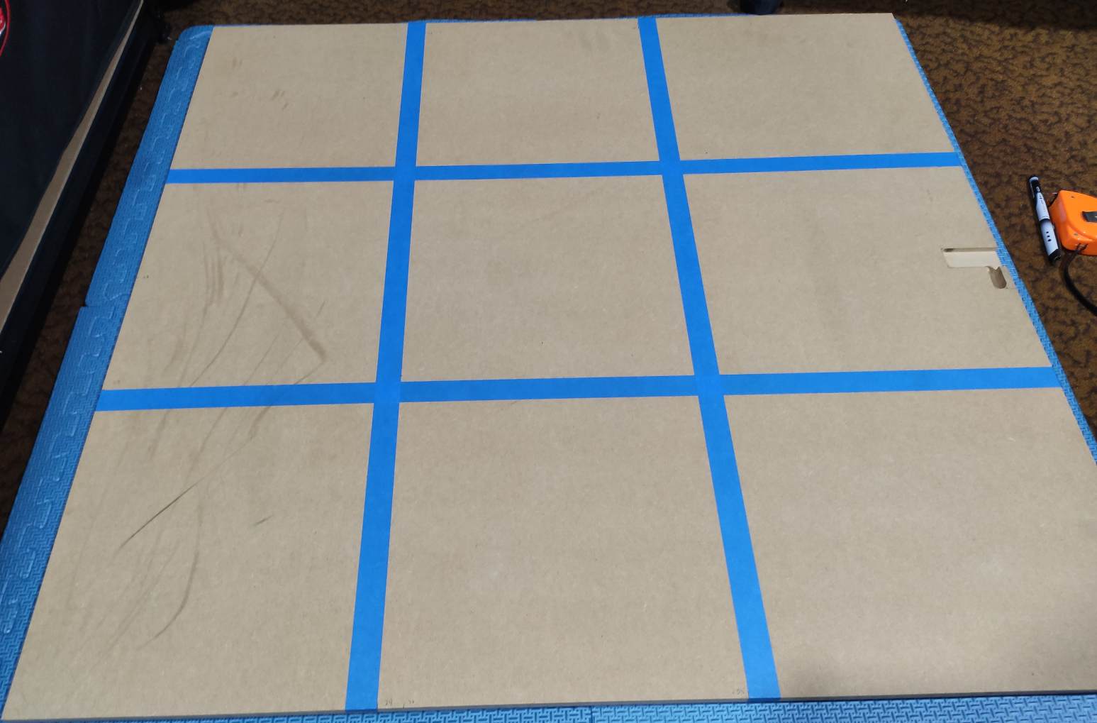
The base is 88cm wide, enough for 3x 28cm tiles across with some change.
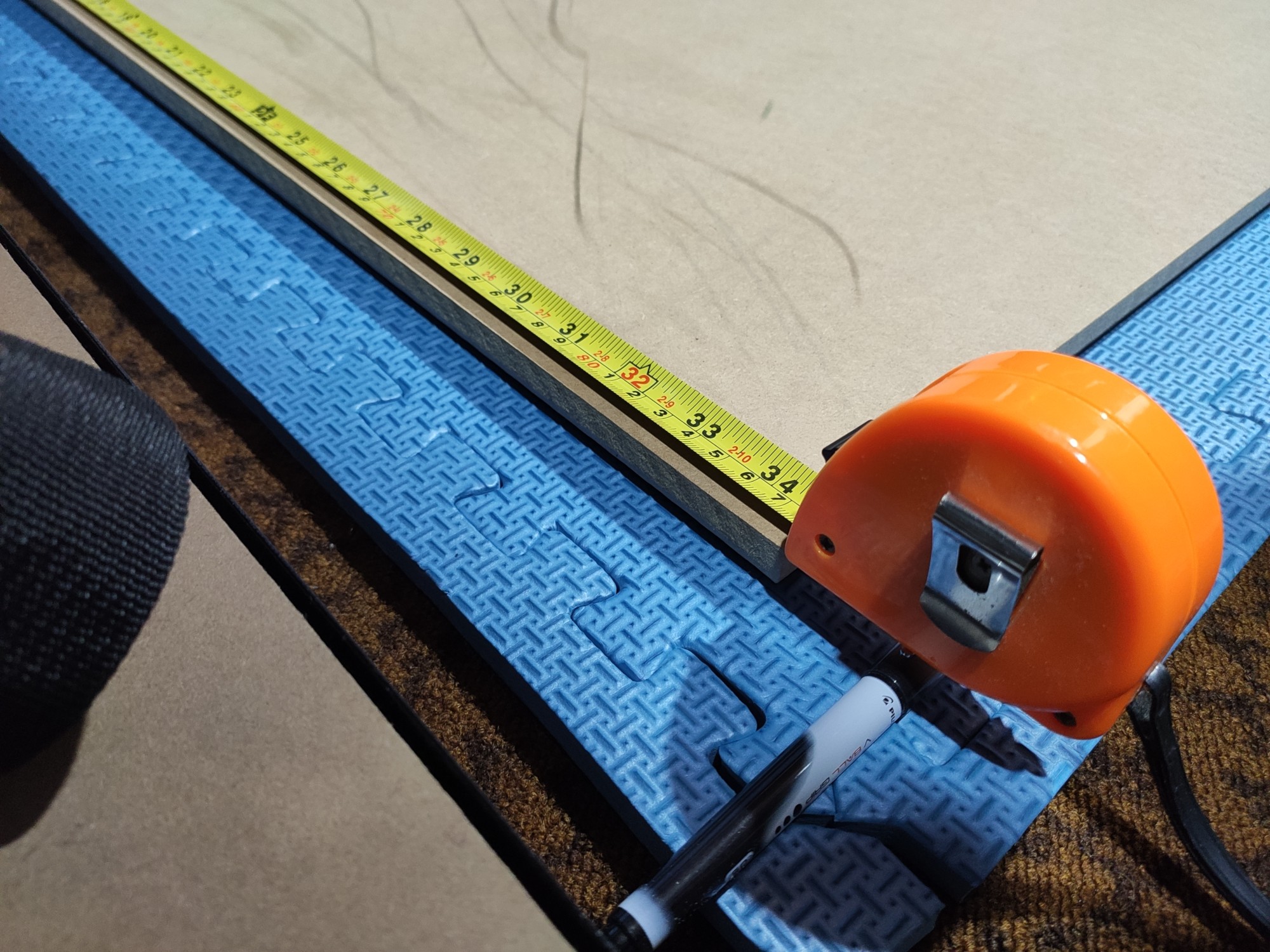
Painter’s tape is quite handy for marking things - in this case the middle column which will contain the up and down pads.
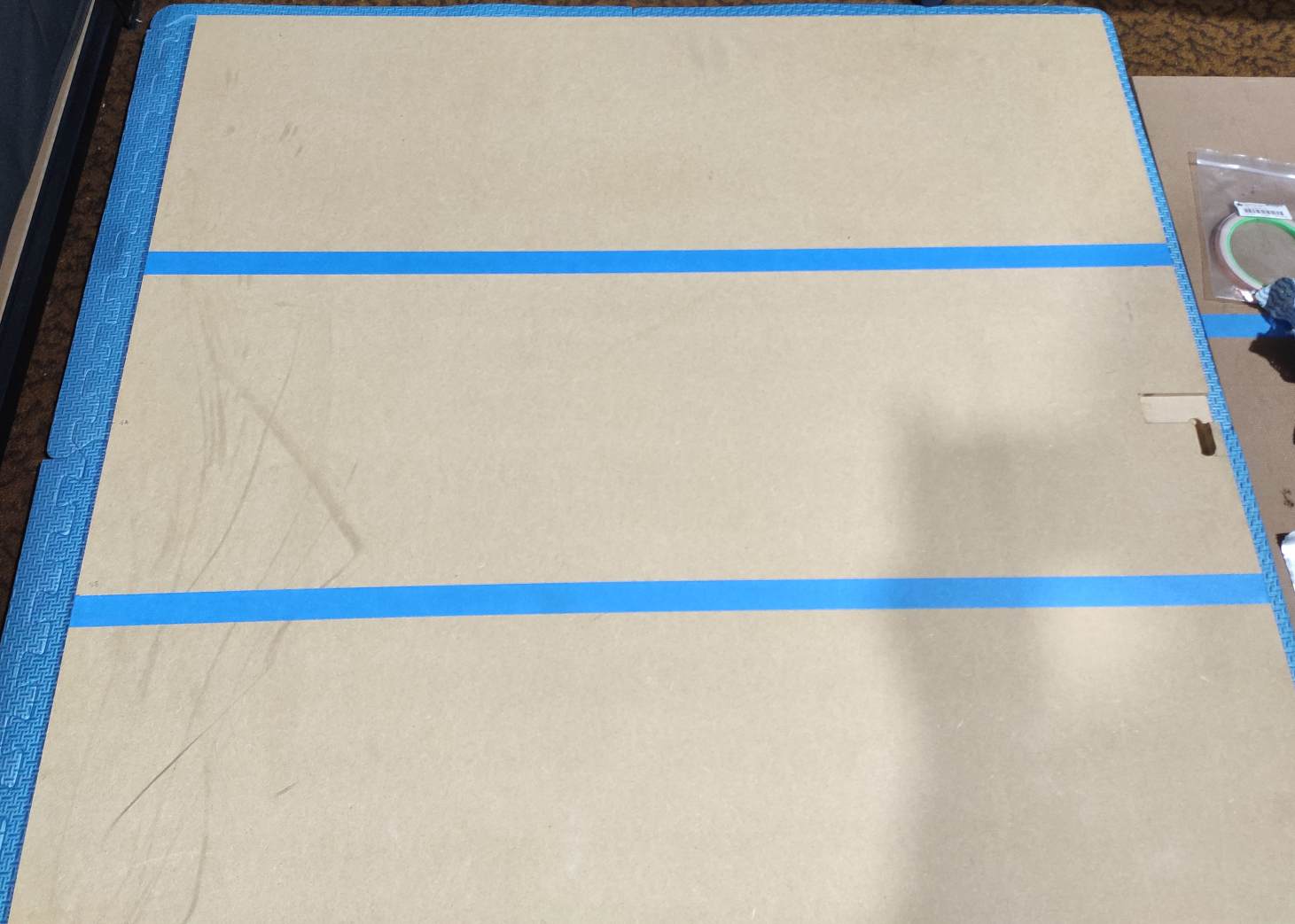
The down pad is right up against the back of the base, which puts the middle row 28cm from there and gives some space at the front for the microcontroller and start/back pads.
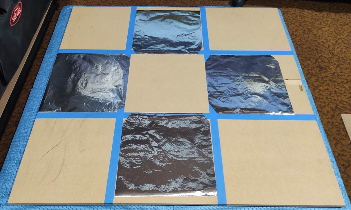
Here’s the pads laid out. I cut the inside corners of them so that there’s no danger of shorting them together, and to make room for a copper foil trace from the down pad up to the microcontroller. I then glue them all to the base using PVA glue. I like PVA glue because it’s forgiving to apply, easy to clean, and an order of magnitude cheaper than most other glues. It’s also very environmentally-friendly, if you care about such things.
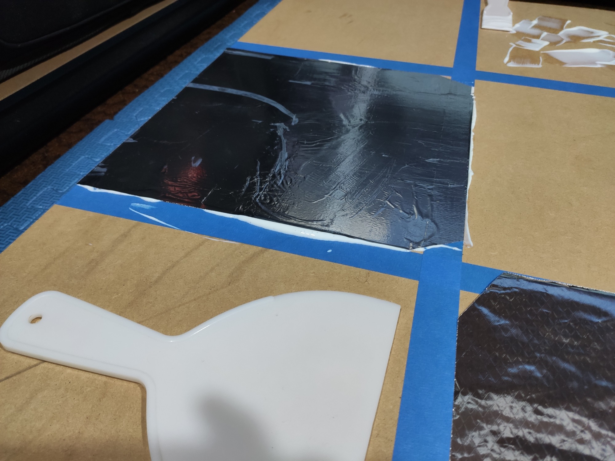
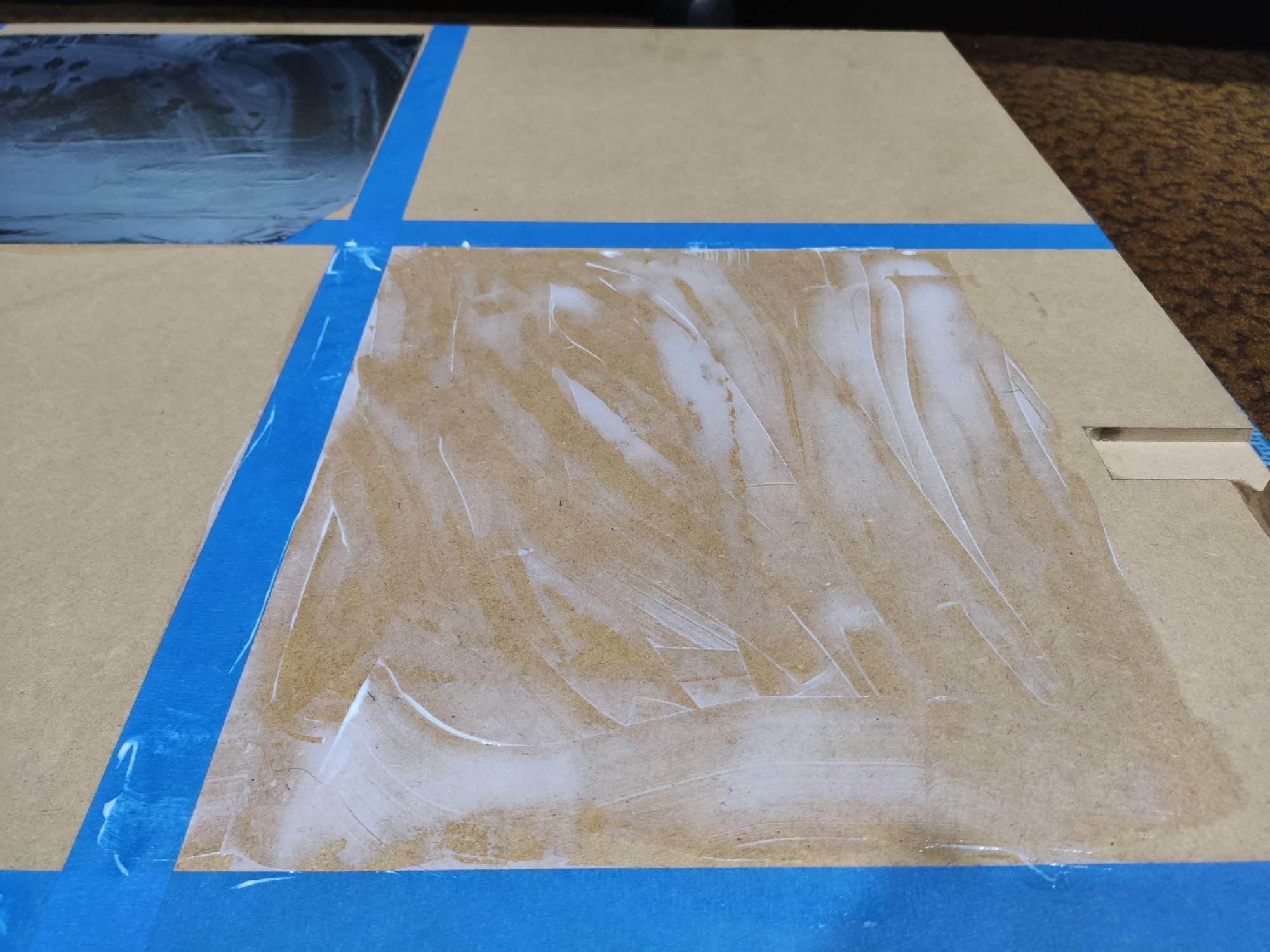
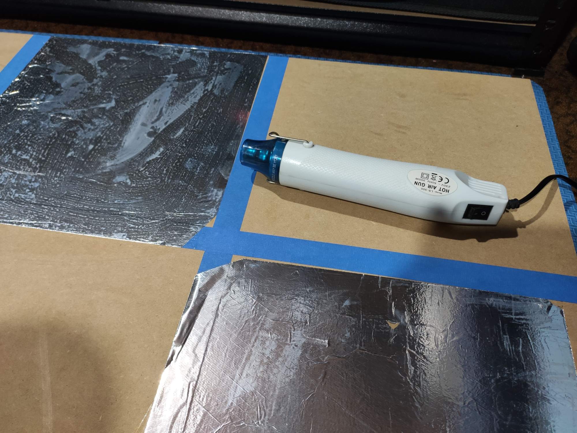
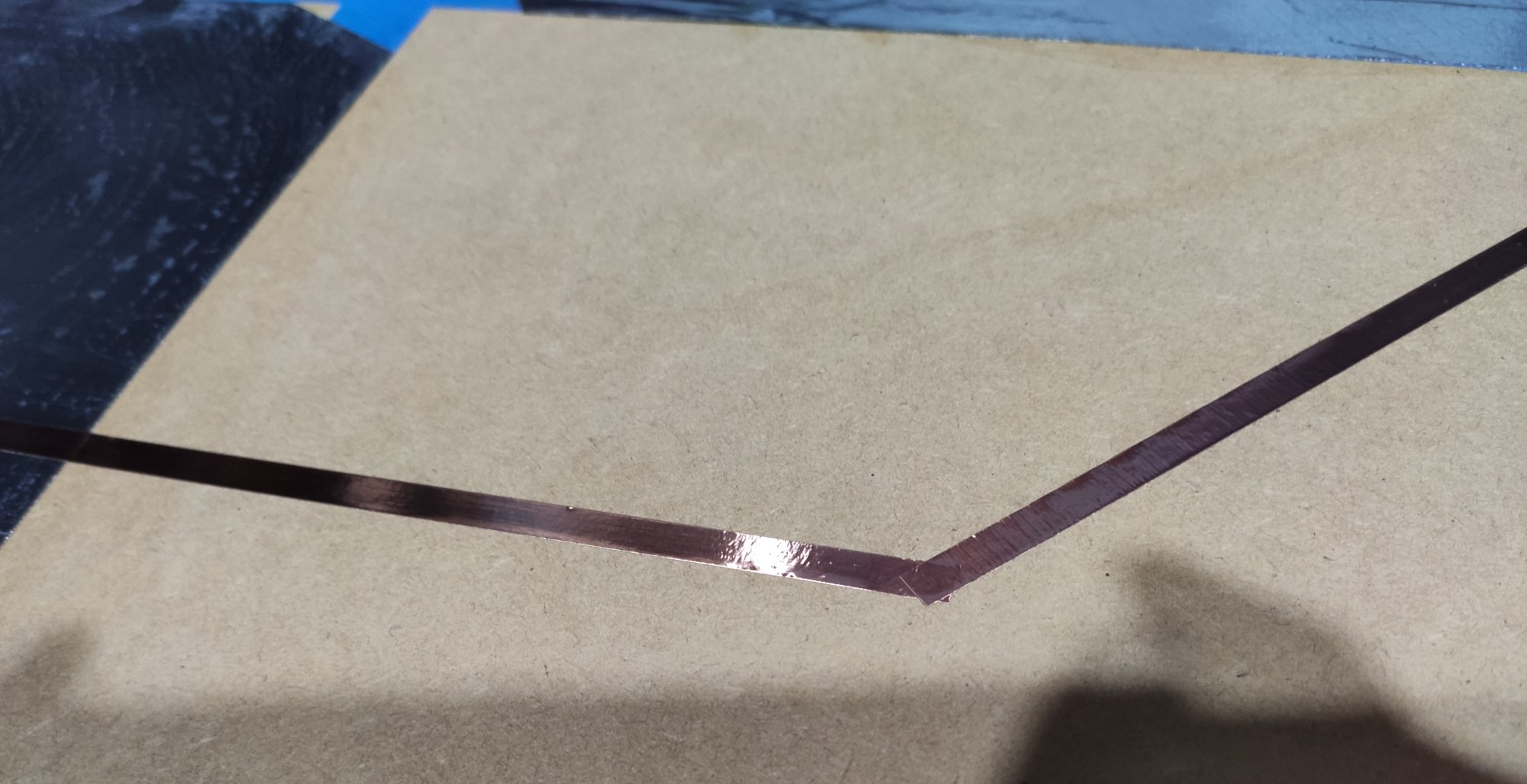
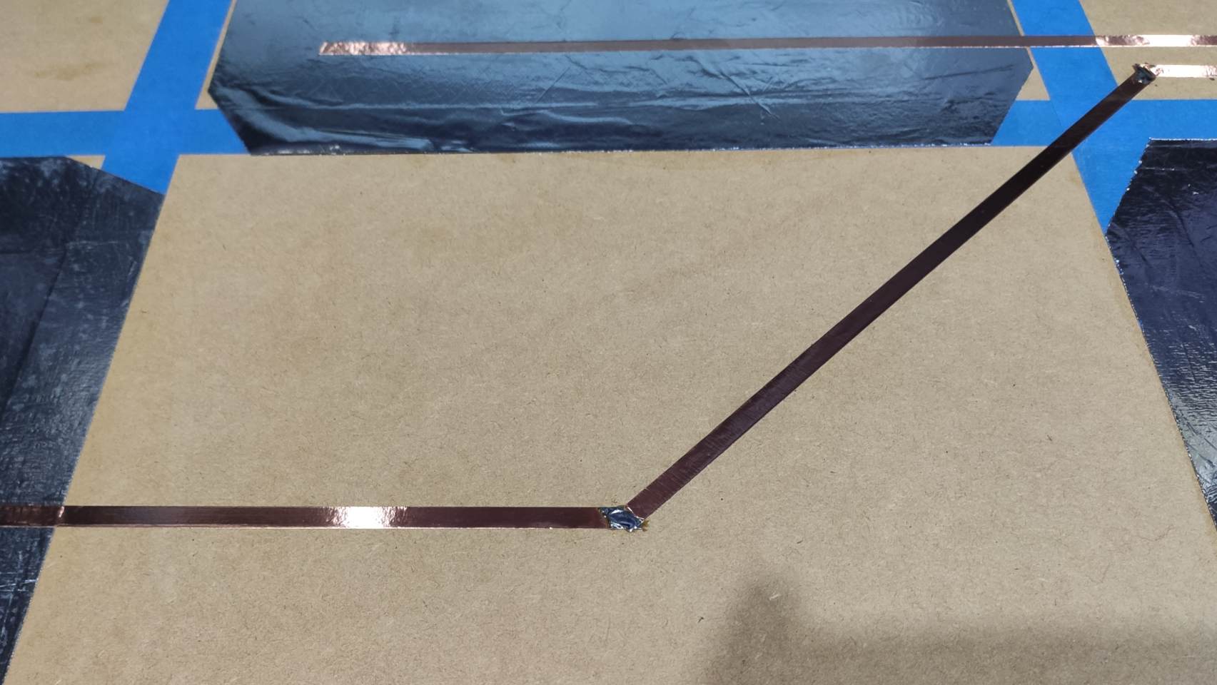
After wiping off some of the PVA that ended up on top of the pads, I lay down some thin copper tape traces with conductive adhesive backing, towards the microcontroller cavity.

This tape has conductive adhesive. The oils on my fingertips interfere with that, unfortunately. Aluminium can’t realistically be soldered, but copper tape is no problem at all. A bit of soldering fixes high resistance on bad tape joints. If you think you’re better than me, you can be super careful whilst handling the tape and make perfect joints without soldering.
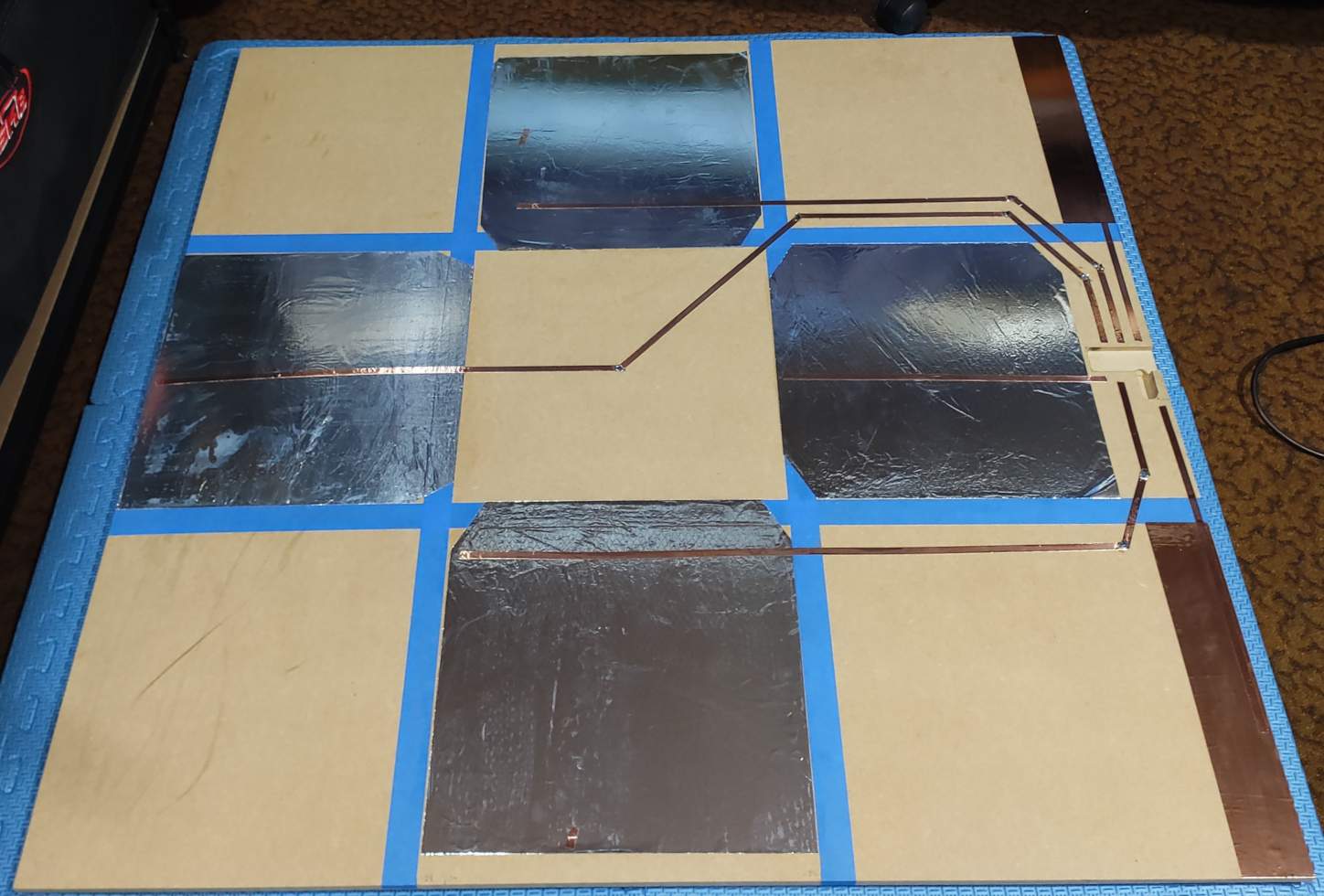
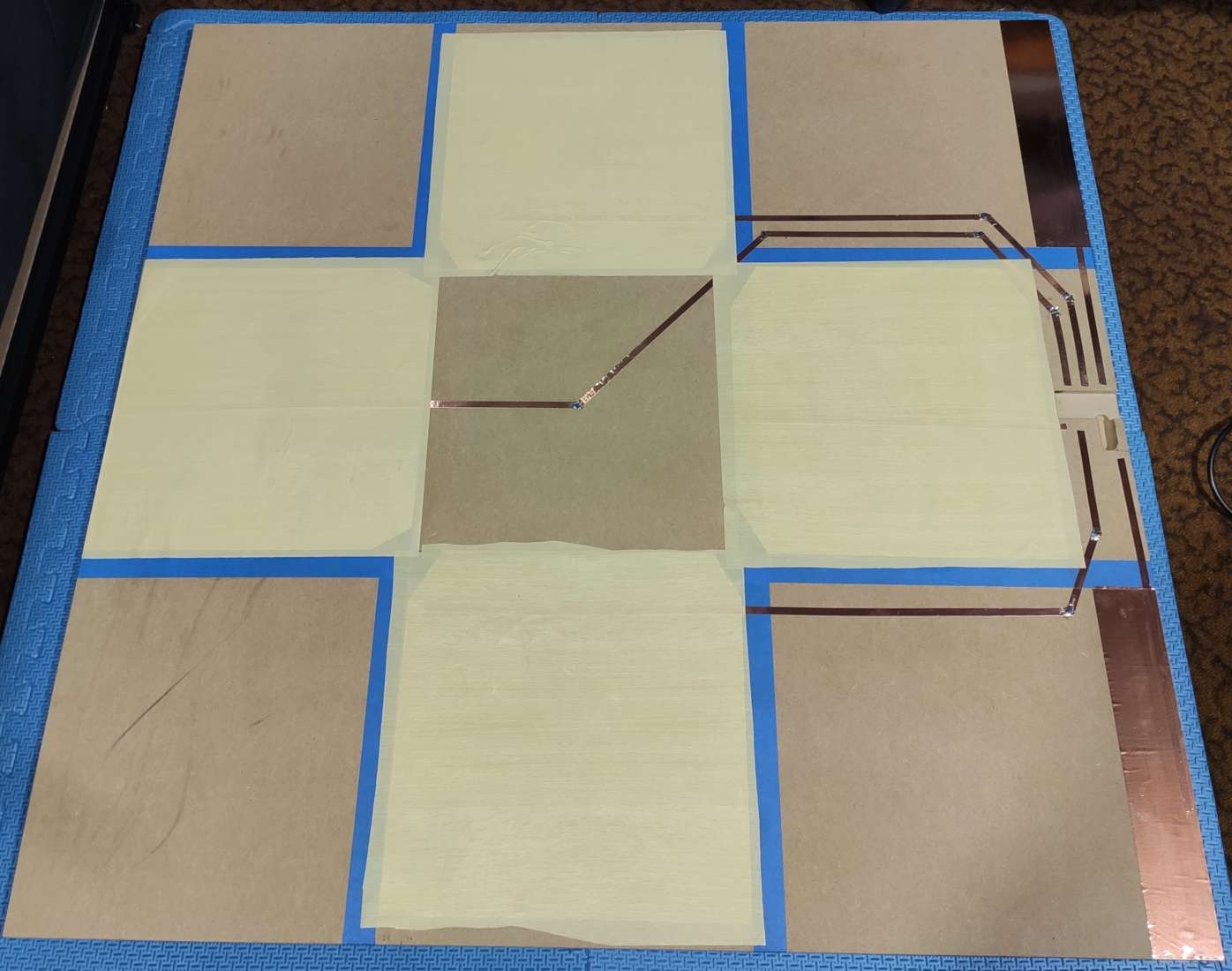
The alfoil sensor pads are the most important part of this construction. They are also the most fragile component, perhaps even moreso than the microcontroller. I cover the alfoil with this PVC craft wrap which is proven to greatly reduce the odds of incidental damage. If you look at the alfoil wrong it might tear and peel a bit, but I’ve played Stepmania on the Fatmat V1 with just this stuff between my feet and the alfoil pads without ruining it.
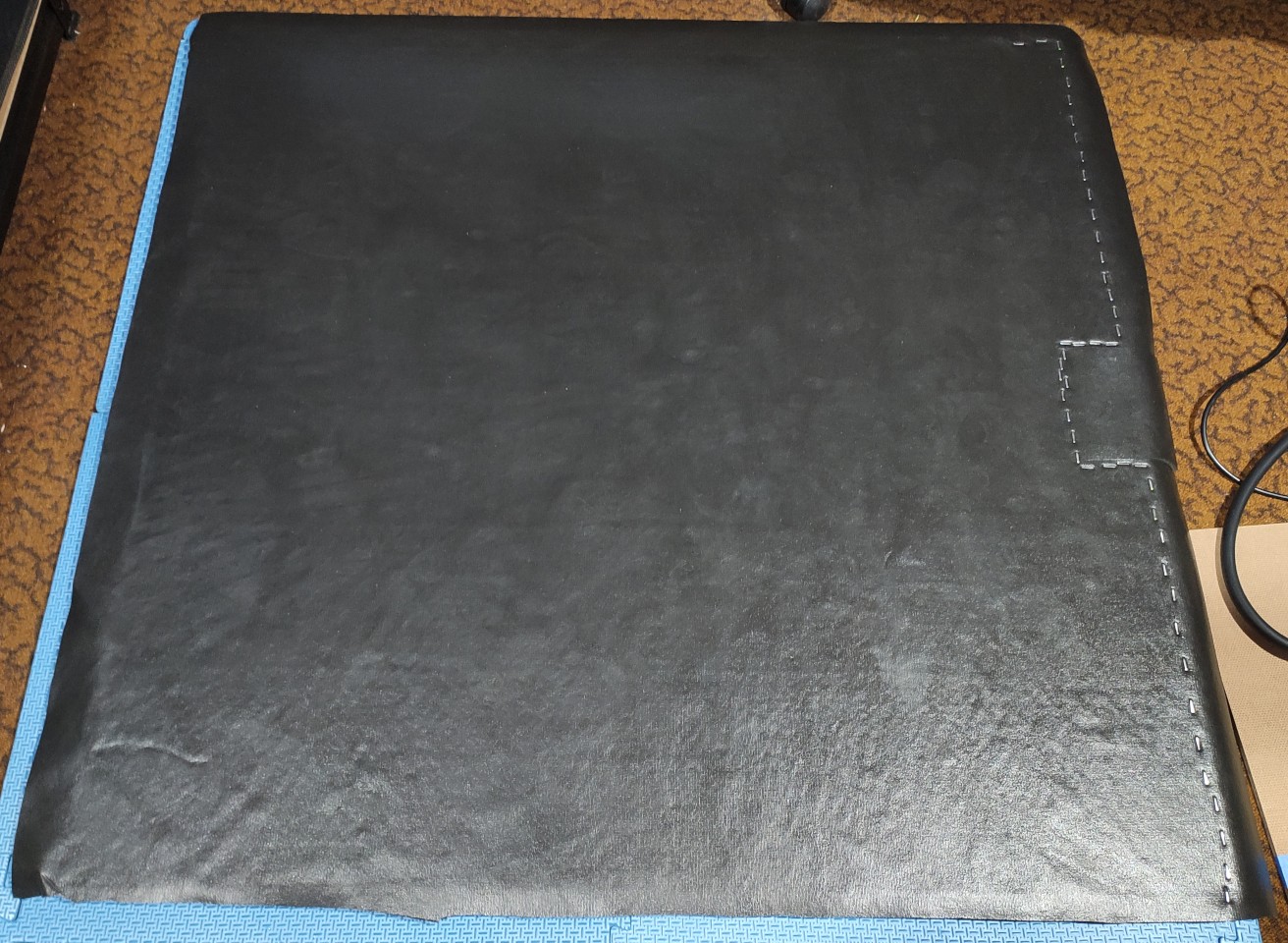
A rubbery gym equipment matting material makes a great playing surface. I glue it straight on top, staple one side, push the bubbles out, and leave it overnight to dry. Please note that I do not glue around the microcontroller cavity, that’s going to be a flap that lifts up. It’d be really awkward if you glued that down, but if you’re using PVA like me you can just rip it up without too much hassle. Such a forgiving glue.
 After an eventful morning pushing out more glue bubbles, the remainder of the perimeter can be stapled on. I use hearing protection from this point onwards as there is a lot of stapling.
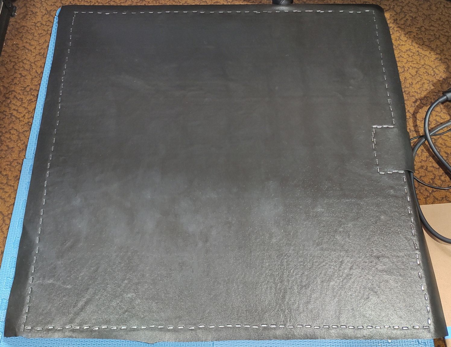
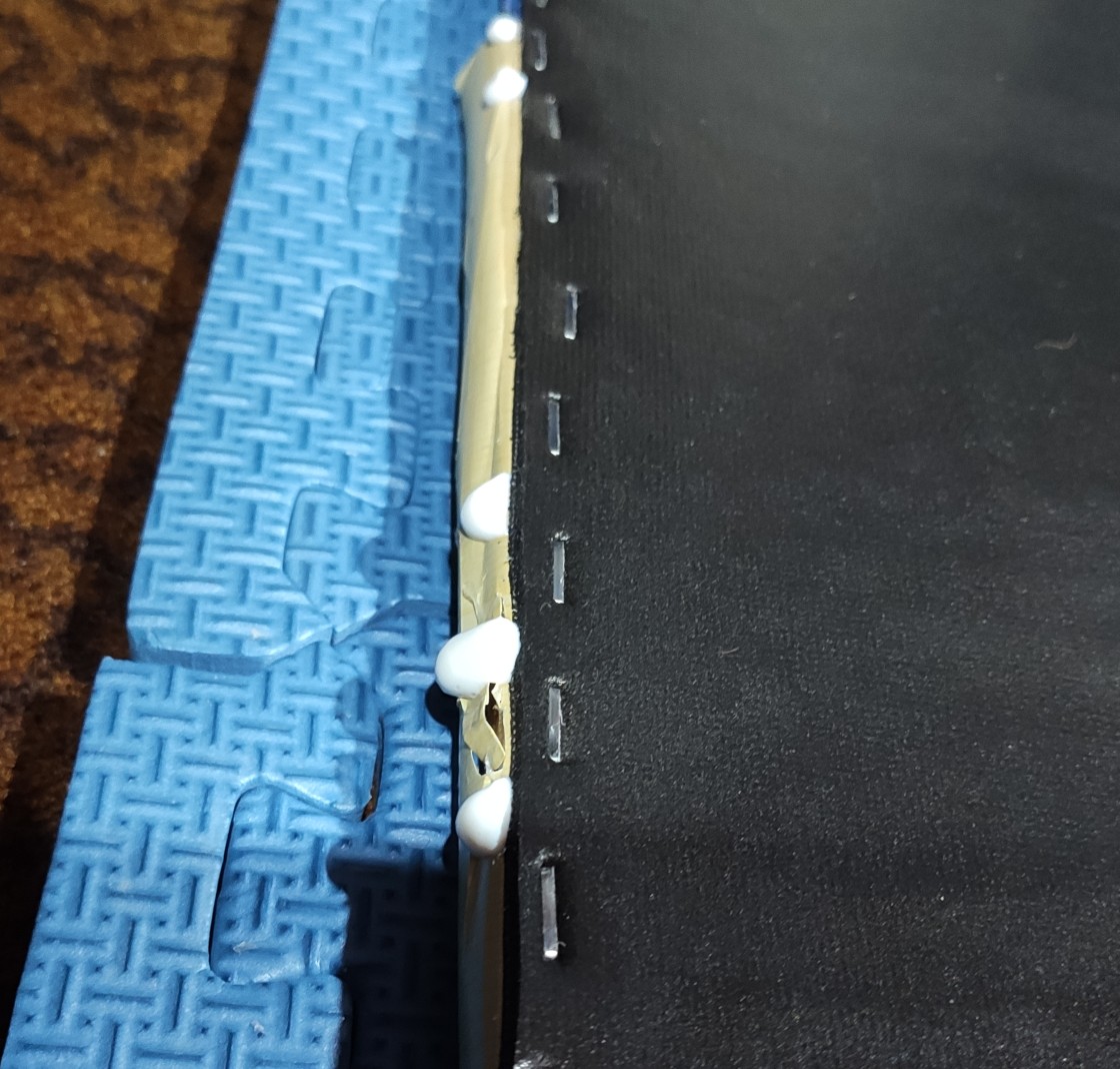
Trim the edges and this thing really takes shape.
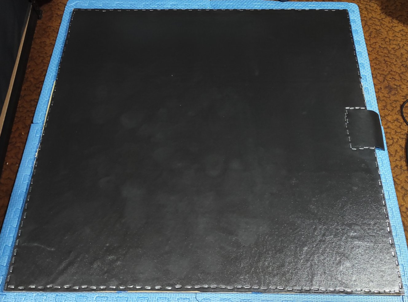
All of this bubble-pushing really brings a four-letter word to mind - glue. Again, I really appreciate how easy it is to clean up PVA, doing this with polyurethane would not spark joy in me.
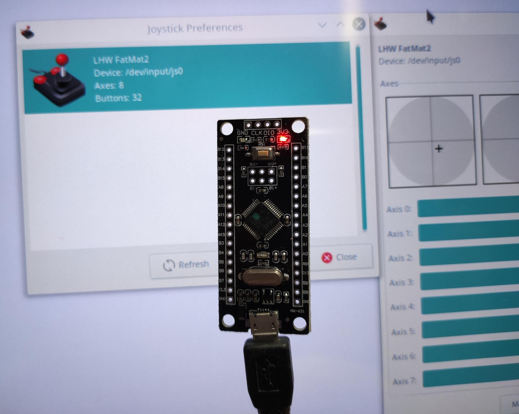
It’s microcontroller time! My current favourite type: STM32F103C8T6-based “Black Pill”. I use Roger Clark’s Arduino STM32 library to make things easy, as well as VSCode with the Arduino extension. If you’re only using my firmware, the Arduino IDE with Roger Clark’s library is enough to compile and flash it. If you’re interested in hacking on it, I highly recommend ditching the Arduino IDE for something less terrible as an editor.
I’m perfectly happy with the firmware I put on this mat’s older sibling so I immediately flash it onto this one’s microcontroller. Naturally, it shows up as a joystick on the computer. Too easy.
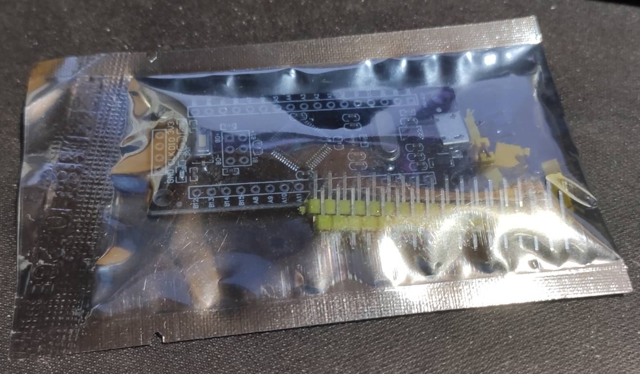
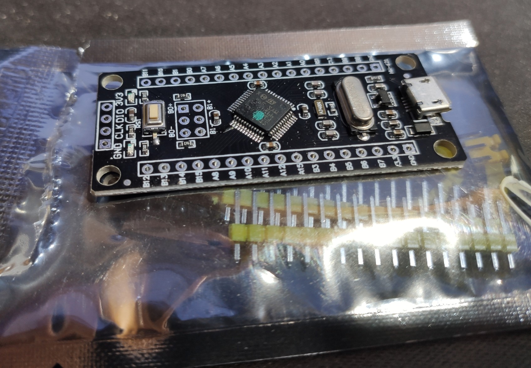

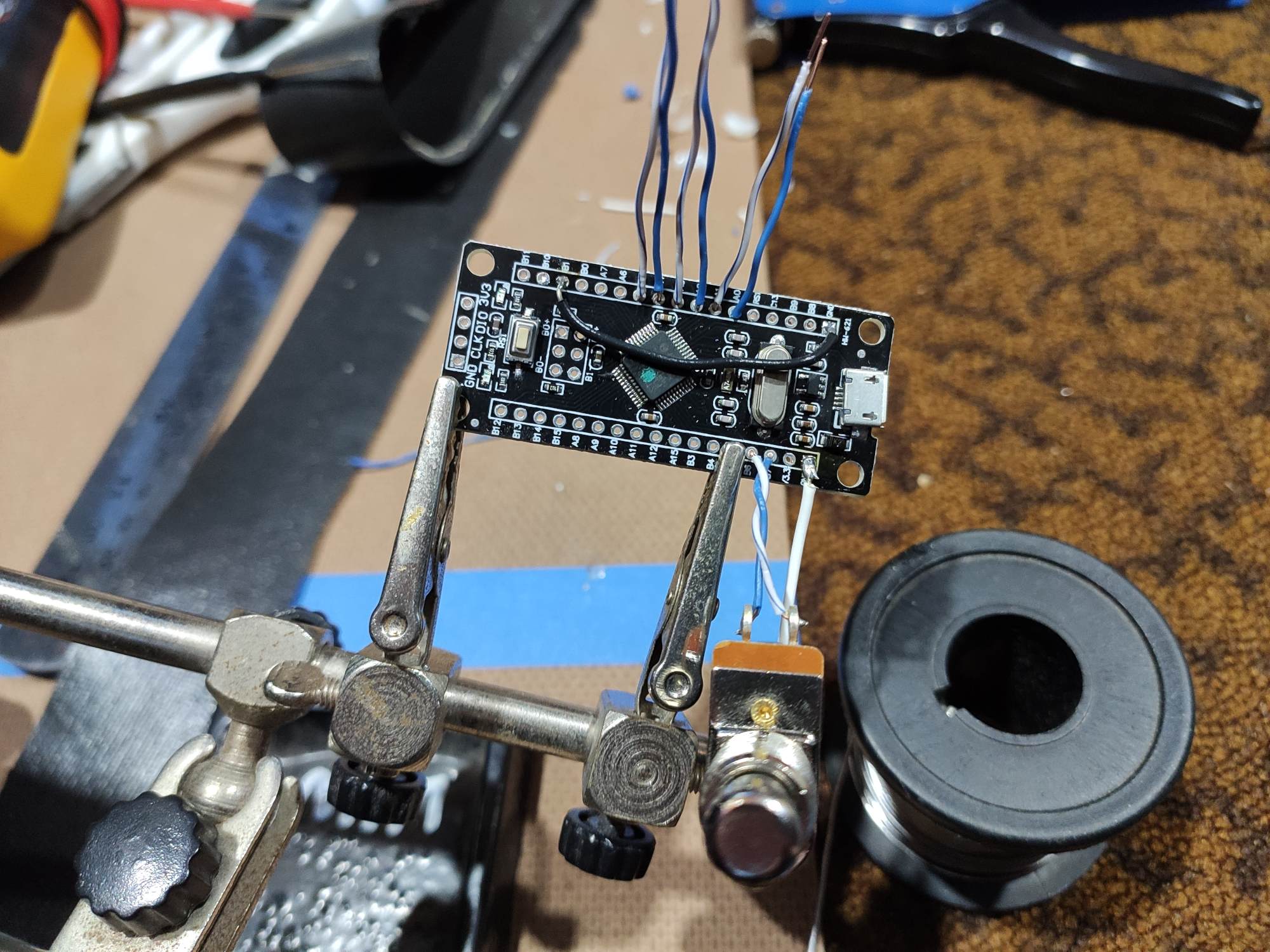
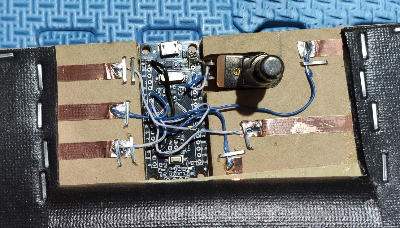
I opt to solder the wires onto the controller before putting it into its home in the mat. It’s a little bit less fiddly this way. I also attach the calibration footswitch since it’s not permanently attached to anything else.
I place the microcontroller in its new home. If all goes well, it will reside here permanently.
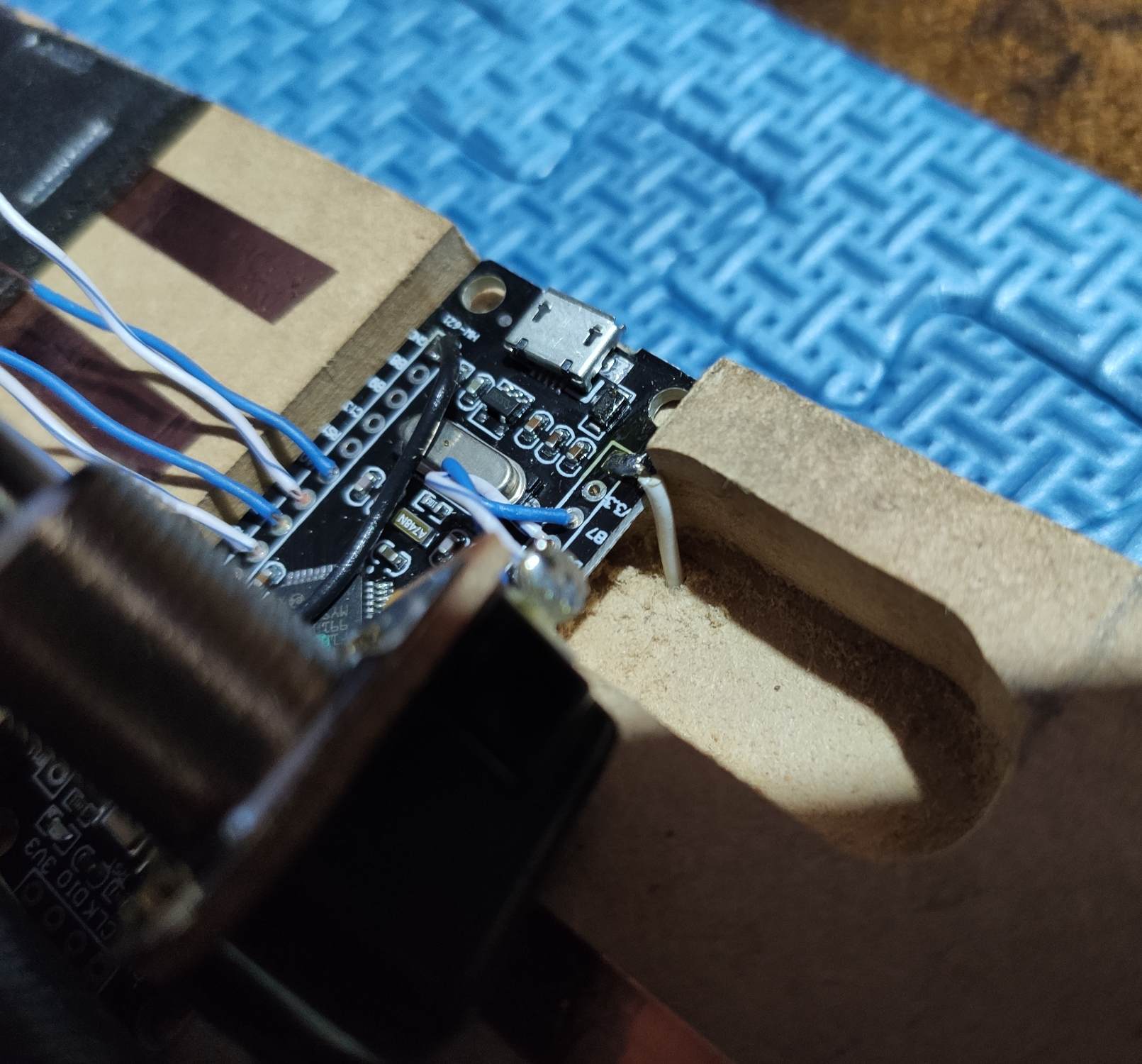
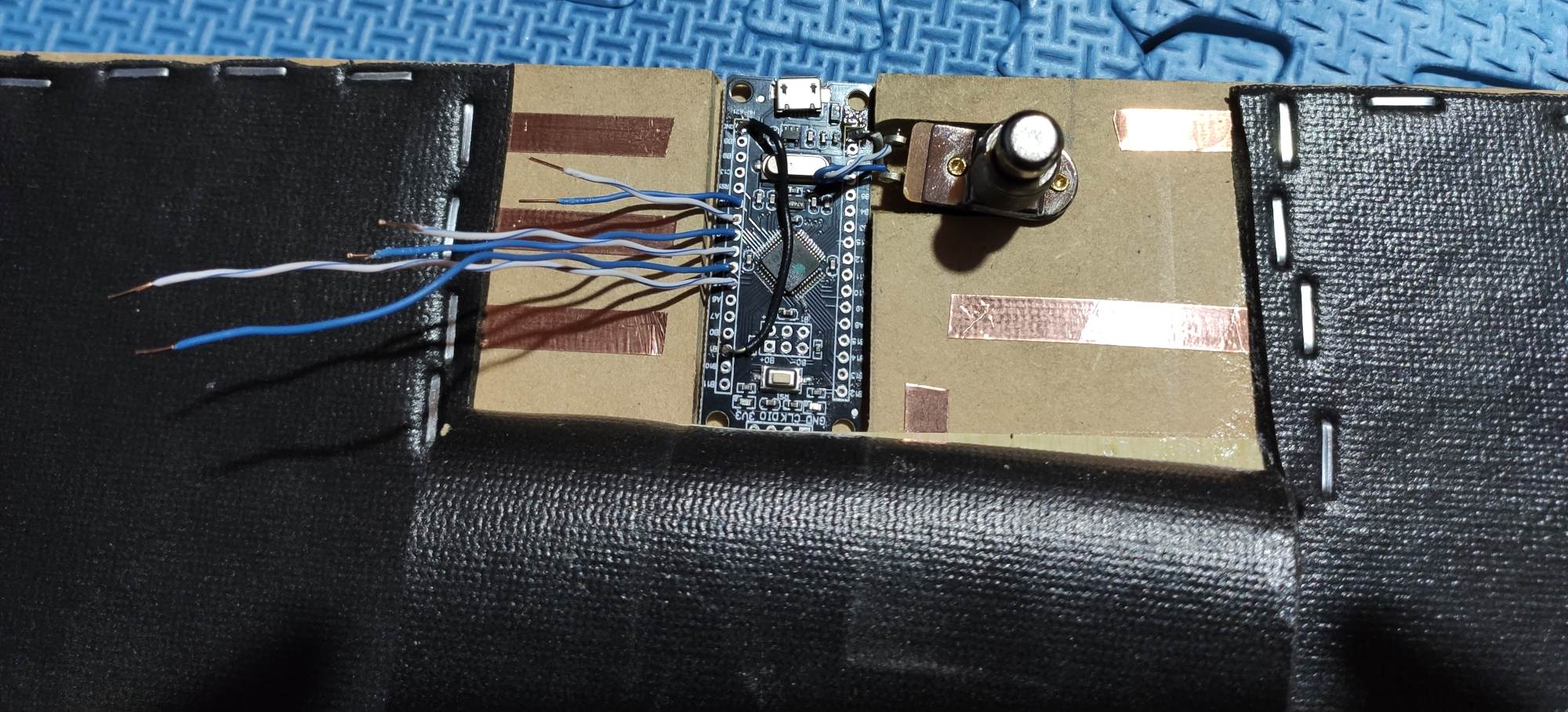
I can solder the wires directly onto the copper tape. This is the main reason I don’t use cheaper aluminium tape. At this point it is a fully functional controller, but there’s still some things to make it better.

When the microcontroller moves, the wires move and lift the tape, which could be a point of failure later5 (plugging and unplugging the USB cable is a bit scary). Staplegun to the rescue :)
I did a screen recording of the sensor steady-state variance without any shielding. For whatever reason, SimpleScreenRecorder betrayed me by instead recording an unrelated section of screen, and I only discovered this after completing the mat, so you’ll just have to take my word for it that the values oscillated by around ±10 on the joystick axes display. It’s actually quite possible to play nicely with that level of noise, and you may be happy to stop here and not bother improving everything by adding shielding.
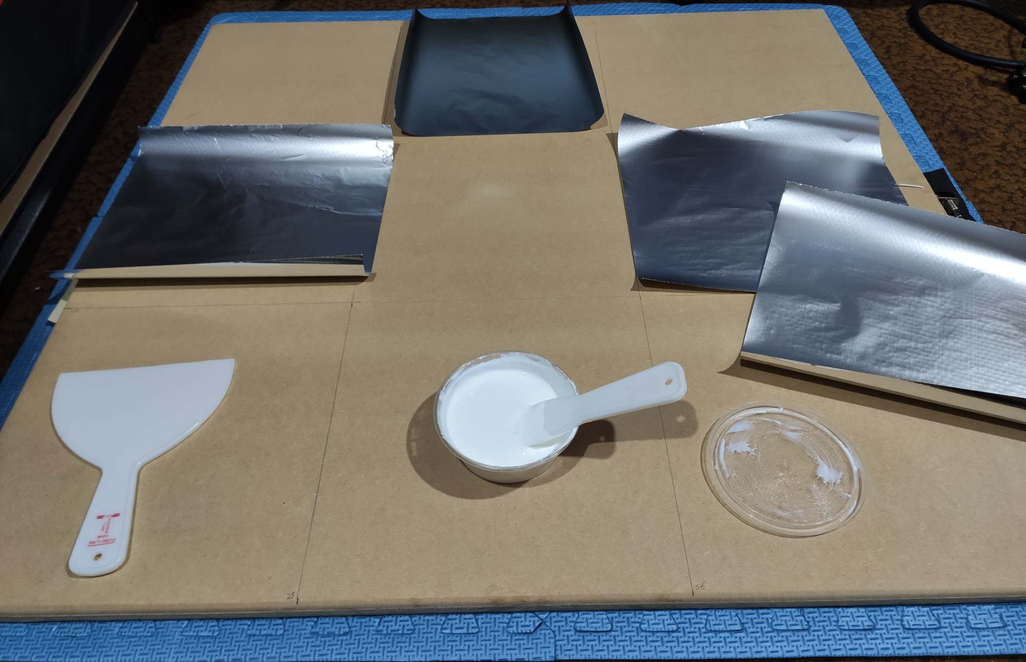
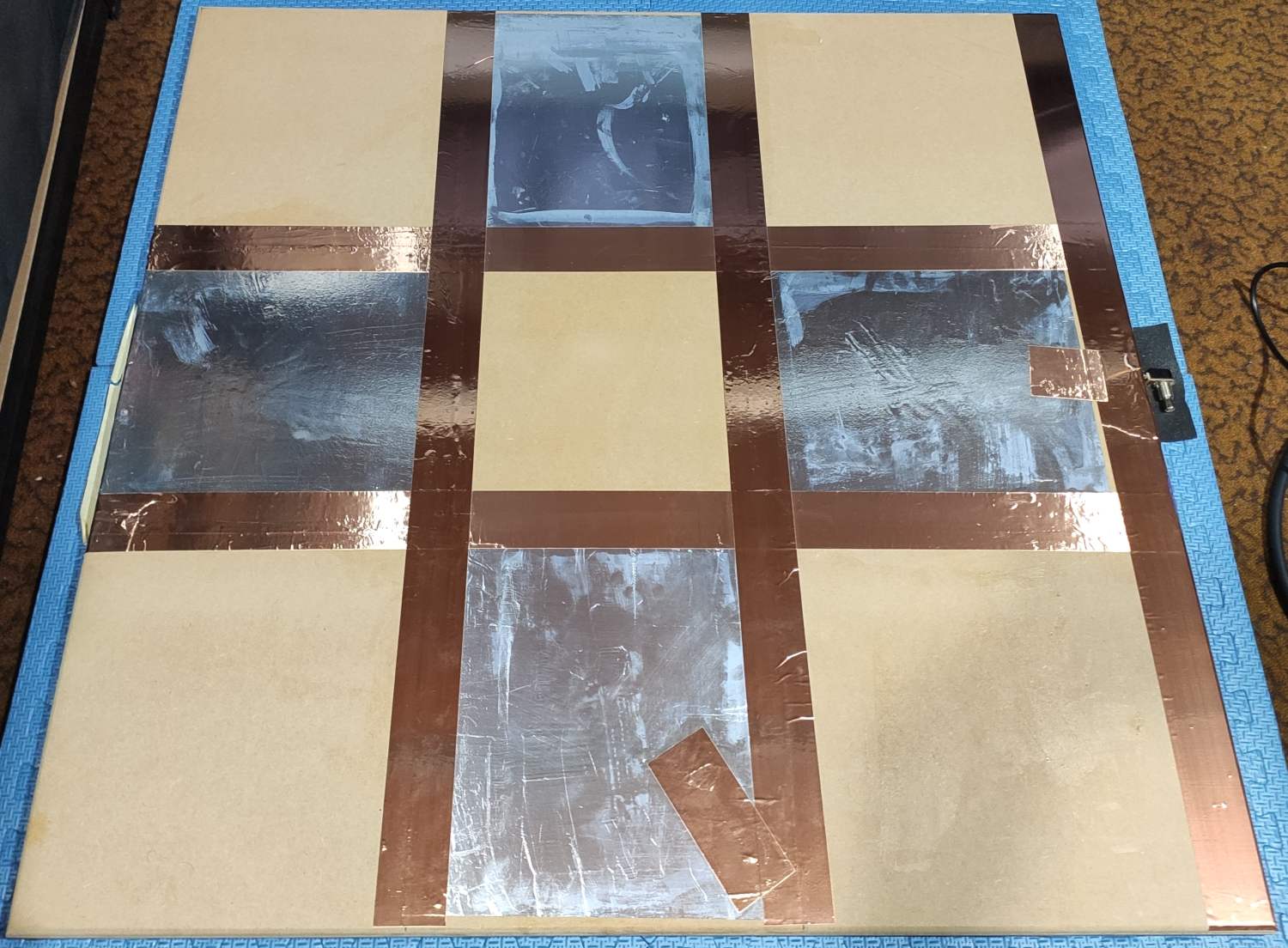
I put down pads on the underside in a similar fashion to the topside sensor pads, except a bit larger and all connected. The white wire connects it all to ground, and I actually needed to set my soldering iron to higher output in order to solder it to the copper tape - the heat just conducts away so well!
As with the topside, I protect the alfoil with PVC craft wrap.
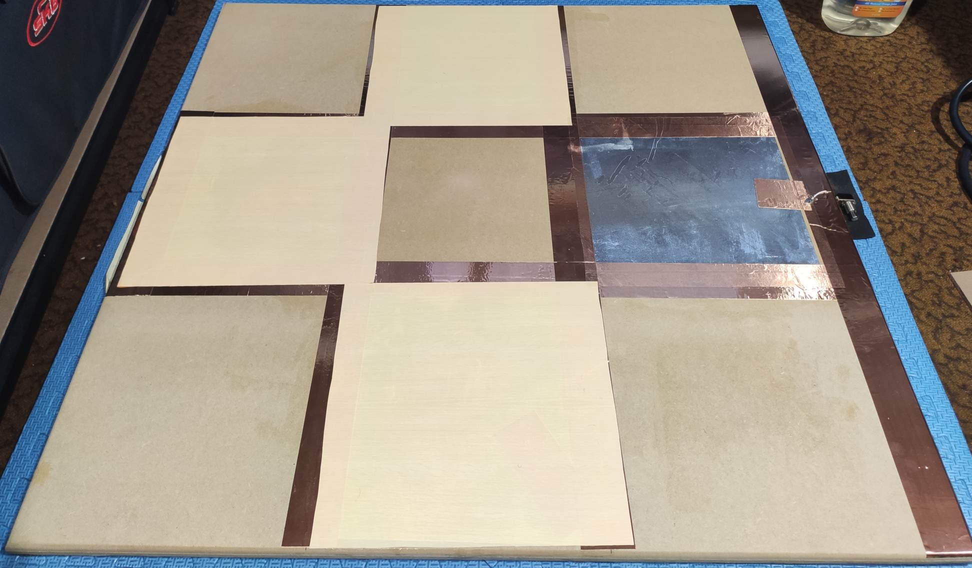
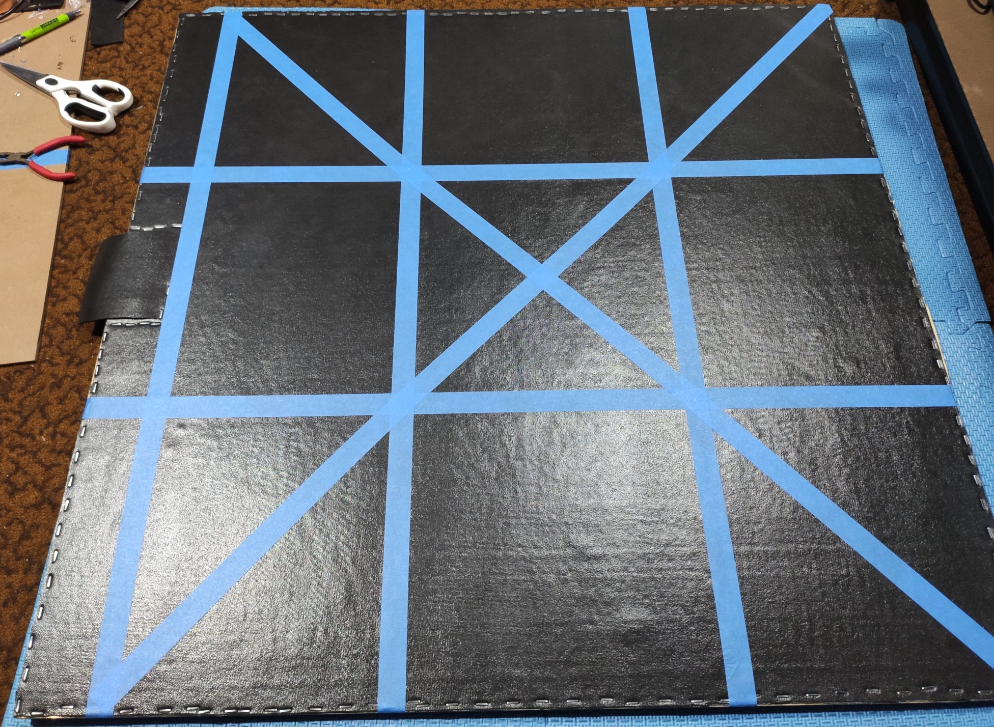
Now’s a good time to mark out the step zones. I still like painter’s tape, it’s very clean and has a bit of surface roughness that’s pleasant to the touch. It’s not likely to stand up to much punishment, but it’s easy enough to remove and reapply if I ever need to.
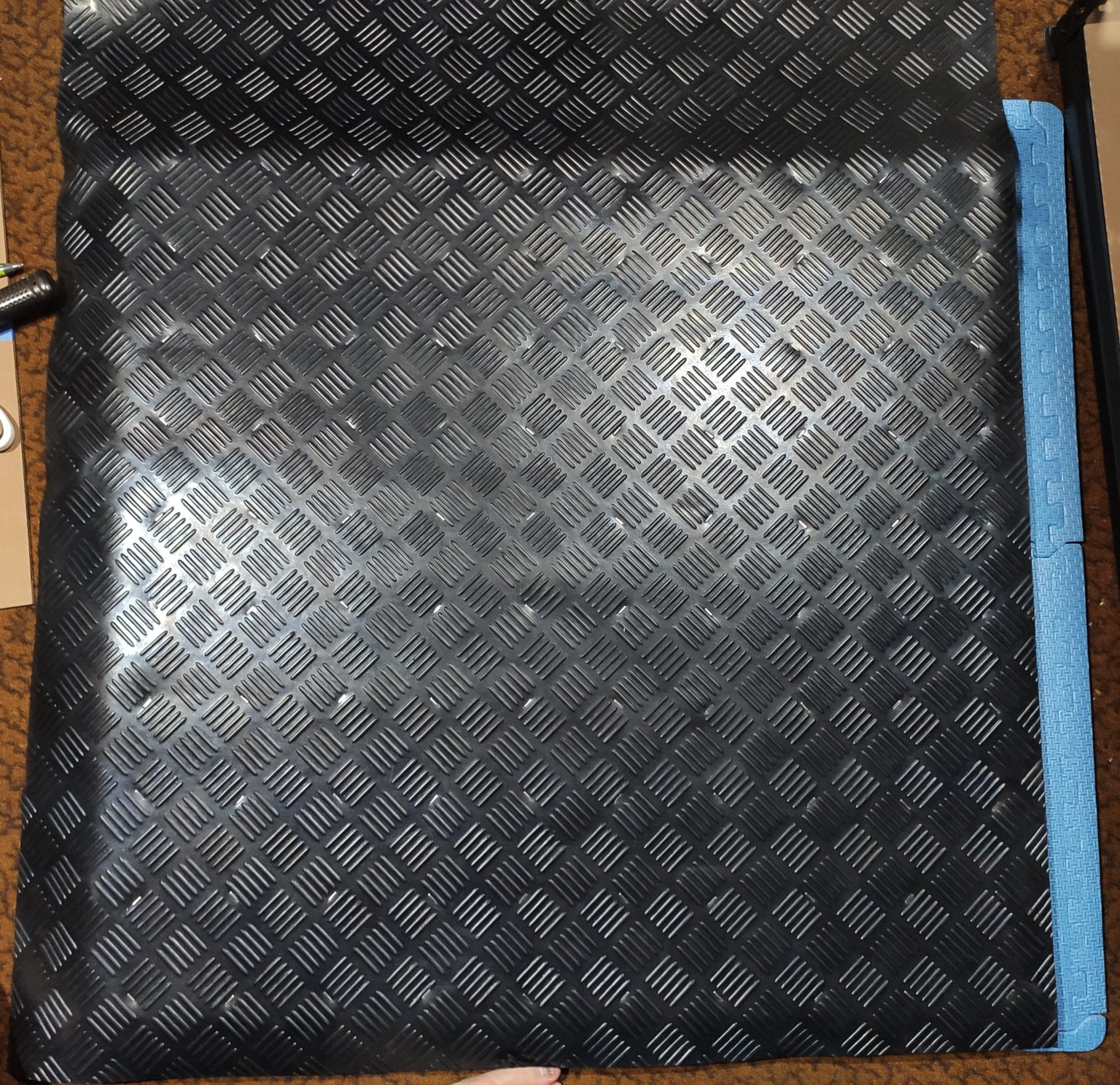
A rubber tread mat makes for a nice non-slip underside. It seems safe enough to staple it over, which I’m happy to do as I can only put up with so much glue on a given project.
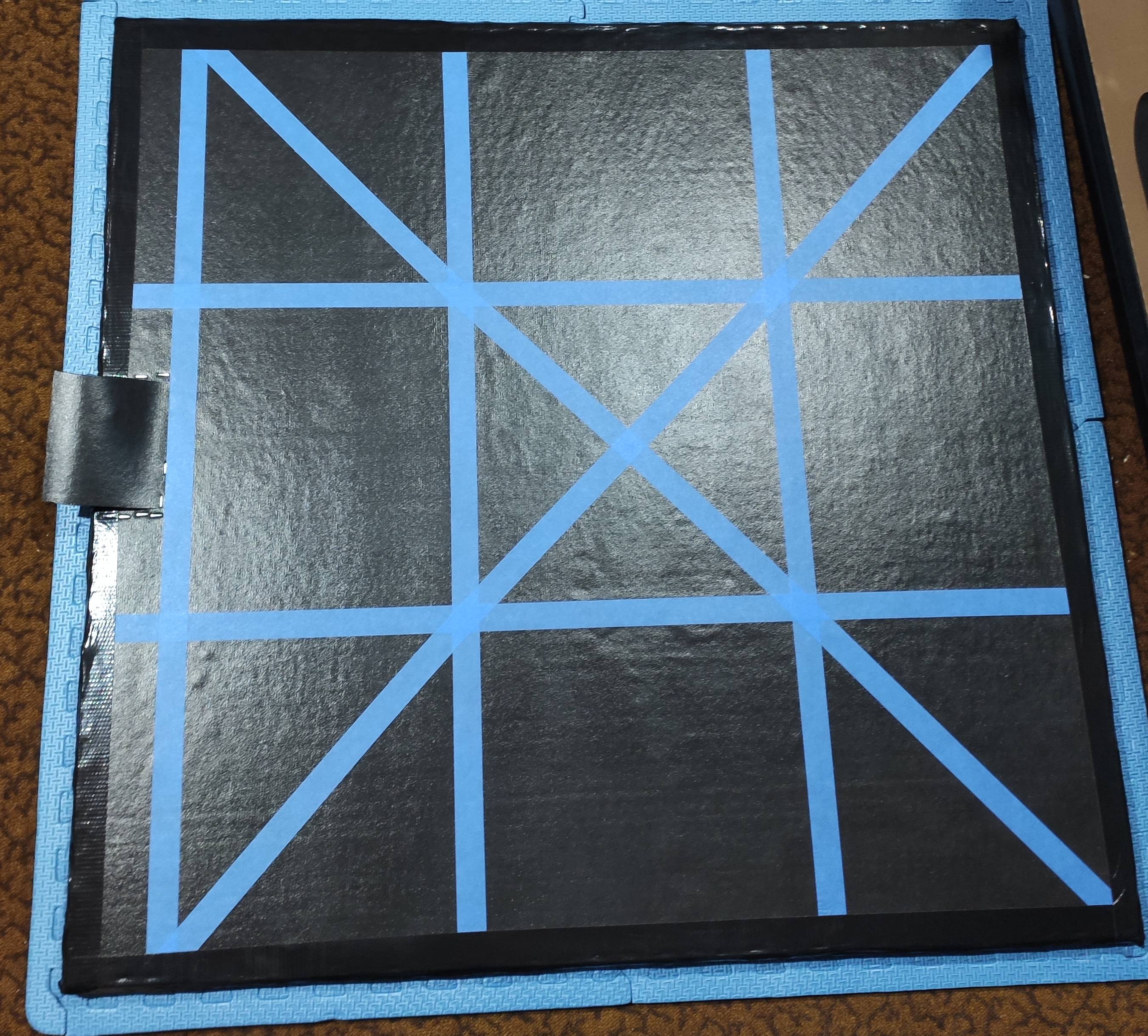
All that’s left is stapling the bottom surface to the sides of the MDF, trimming it everywhere and running gaffer tape along the edges to prevent any accidental peeling of the top or bottom surfaces.
Results
With the shielding on the underside of the mat, the pad sensors now give very stable readings. In the clip below you can see just how sensitive they are to player presence (Right pad is Axis 3, Top pad is Axis 2):
As you can see, the signal:noise ratio is so high you could probably add another 2cm of material on top and reliably sense a player’s foot on top of that!
This mat plays about as well as its older sibling. I’ve only played a little bit of doubles and couldn’t really tell if there’s noticeable variance (more likely to stem from the microcontroller than the construction), and so far it seems every bit as awesome as the mat I’ve been playing on and loving for most of this year.
On less robust capacitive pad setups, it’s often difficult to tune the sensitivity such that rolls are possible without making holds inconsistent. With 16mm of MDF, and shielding on the bottom, all is well. I’m still bad at rolls though since I played with them disabled on inferior mats and only recently started playing with them enabled.
As for streams, it’s not the limiting factor in my (lack of) success yet!
And yes the webcam is probably delayed a bit in both of those clips. I can’t be bothered trying to sort out sync offsets for it.
Future Mat Considerations
Pads
Time is money! PVA and alfoil take a relatively enormous amount of time to work with, I don’t think I’ll ever build a full mat with them again. Copper tape is much faster to work with and the price probably works out pretty good if I ever calculate my labor costs. For a yet more rugged approach I’d consider cutting up sheet aluminium and using buttonhead/countersunk screws to attach them to an MDF base, and just have a 900x900mm sheet on the bottom for shielding. Might drive up weight and cost, and require a different surface, but it would be virtually indestructible in situ, and possibly much faster and easier to construct.
Surfaces
I really like the rubber tread matting on the bottom, and I really like the rubbery exercise top surface for foot/sock play. Rubber tread matting on top might make it suitable for shoe play, though stapling it on top is not a sensible option so it would have to be glued. One thing I’d like to try at some point is covering an entire mat in something like Line-X, perhaps Bullyliner.
Bases
Thick MDF works very nicely for a number of reasons. 32mm of it on the Fatmat V1 seems to work well enough to not require a ground pad underneath, perhaps a full 32mm thick base with grounding would produce stellar signal-noise ratio. Stacking 2x 16mm boards and screwing them at strategic spots should do the trick. It would also open up the ability to run wires in the middle of the base which should help signal matters even further.
Software
The current set-zero-button calibration method, while simple, is not going to cut it for a wide range of players. In order to accommodate people with significantly different foot capacitance than myself7, as well as the differences in foot/sock/shoe play, there must be a way to tell the controller what constitutes a “press”. Unfortunately, I don’t have a good solution for a calibration routine on the controller alone - I’d much prefer to integrate something into Stepmania that would show on-screen arrow prompts. If I’m modifying the game though, I could also just ditch discrete calibration entirely and use the axis values to make judgement calls in-game, using the knowledge of what it’s expecting the player to do to determine press states. “Oh, he’s supposed to press left now, and the left pad went from -432 to -440, this seems reasonable, it was probably not touched before and is now touched”, “Oh, the right pad value has been low for 30 seconds now. A normal drift compensation routine would suspect this is the new zero-state of the sensor, however as the game I know that there is a Hold ongoing so of course the player will still be on it” and so on. Naturally this will be useless for any other games which don’t have such integration. Does that really matter? Who knows.
Other
Portable mats for travel would be nice. I’m teasing out ideas for step sensing on 30x30cm garage plastic flooring tiles, which pack up quite nicely from a purely mechanical standpoint. Softmats that don’t suck are another avenue, perhaps sandwiching thick foil pads between two heavy-duty PVC tablecloths would be sufficient as a starting point. If I could manufacture large conductive prints like the ones within chinese softmats, I’d be able to prototype some fiddly exotic ideas that are far too much manual labor to test with foil tape. The closest I’ve seen is screen printing with conductive paint which is neither cheap nor easy, so I’m not following that up for the time being.
Closing thoughts
This writeup took almost as long as actually constructing the mat. I’m glad to be done with it so I can actually play some Stepmania again. Hope you found this post useful or at least interesting in some capacity!
-
I’m not giving you a link for this one. If you don’t know what it is, the comparison is worthless anyway, and clicking the Stepmania link is more meaningful. Also, I’ll be calling it DDR in the rest of the post, because Dance Dance Revolution is too long to casually throw around. ↩
-
It is possible to play with computer keyboard, or any gamepad capable of connecting to your computer. This is clearly an oversight left in for testing purposes or as an accessibility option for paraplegics, yet an alarming number of able-bodied people choose to play this way and fail to see how deeply wrong and abhorrent this is. ↩
-
In The Groove is a commercial arcade game cabinet based off Stepmania software. If I were to refer to it elsewhere, I’d call it ITG, but I won’t, because the only thing I wish to convey about it is that you can find the machines and play Stepmania on them. ↩
-
When a player stands over multiple pads, their body is no longer merely floating relative to ground, but has a weak tie to each pad. Pads are grounded when not being measured, so the player’s body effectively has a stronger capacitance to ground as far as the sensor is concerned. The difference can be mitigated by having non-sensor ground pads everywhere the player would step, however it would still be different while they have one foot in the air. ↩
-
This also shows up on a much smaller scale when soldering wires to PCB pads and traces - while the copper to fibreglass adhesion isn’t particularly weak, a bit of mechanical stress is quite capable of separating them. It can also happen with chip on board stuff that hasn’t been potted yet. Mechanical reliability is just as important as good electrical conductivity for joints in the long run! ↩
-
Against my better judgement, here’s the full recording of me playing that track. ↩
-
Yes, different people have notably different capacitances around their bodies. Older people sometimes struggle with capacitive touchscreens not recognising them. Moisture content is a large factor in this, though there may be some other bioelectric effects involved. ↩